Continue to Site

Eng-Tips is the largest engineering community on the Internet

Intelligent Work Forums for Engineering Professionals

  • Congratulations IDS on being selected by the Eng-Tips community for having the most helpful posts in the forums last week. Way to Go!

VFD cooling water sump pumps' performance curve misunderstanding

Status
Not open for further replies.

silebi66

Chemical
Dec 15, 2012
71
Dear professional master members:

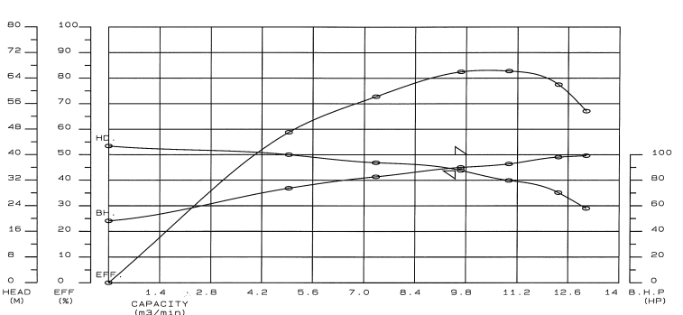
There are four horizontal pumps located above the cooling water sump in our plants,and the cooling water be sucked out from the sump through the vacuum vessel. I also attached the pump performance curve from the vendor for your reference. Since this the VFD pump, the frequency may vary from 60 Hz to 50 Hz.

For example, there is no flow at 1796 RPM, but the vendor report show the head is 42.7 m. Also, the pump is tested from 1796 rpm to 1786 rpm (from 60Hz to 59Hz ?). I am not sure this is right report or not since there seems somewhat different from other vendor's curve. ( other vendor show the each performance curve from one fixed speed at a time)

I also went to the site, and test the one of the four pump with full speed 60hz (while the other three are also running). The measuring electrical current is around 110A (the rated current is 118A), and the flow rate is 560~570m3/hr (close to the rated flow rate).

But, after the four pumps run for a period, the flow rated measured for one is around 420 m3/hr, and the electric current reading is around 80A (way below the rated electric current 118A). I guess the reason for this difference. It may be the four pump running together with the different suction pipe, such as four pump run in parallel?)

Please give me some hint or light from this misunderstanding report.

Thank you very much.
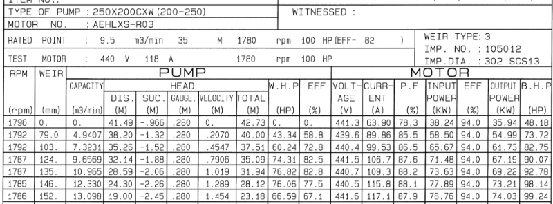
2016-10-08_184050_wo7mcu.png

2016-10-08_184142_k6pdas.png

 
Replies continue below

Recommended for you

Here are a couple of things.

If the pump runs at 60 hz the rpm should be somewhere around 1750-1780 rpm. At 50 hz it should be around 1450-1480 rpm assuming you have a direct coupled standard induction motor driving these pumps. This is a fact that cannot be changed.

A sketch of the layout would be good particularly if you could mark up where you are measuring the flows.

My guess is that the system design limits the flow rate that can be pushed through the system by a rapidly increasing head. As you bring on more pumps there is relatively little increase in overall flow rate because of the head limits of the individual pumps is still the same but the system head is increased by the increase in flow. Somewhere it finds an equilibrium point. In this case each pump will be doing about 420m3/hr and the system head must be about 38 m.
By the table the pumps should be running at about 90A but you suggest that they may be a bit lower than that. There could be many reasons for this. One thing to check is that they are all running at full speed or at least at the same speed.

A couple of things to remember about parallel pumping and these comments assume that all the pumps are the same size and model and operating at the same speed. The total head that the pumps can handle does not increase as you add pumps, it stays the same as one pump. However the flow rate possible increases as you add pumps but so does the friction head developed in the system into which you are pumping.
In a friction-less system the maximum flow= the maximum flow of one pump x the number of pumps.
However because we do not live in a friction-less world the maximum flow rate obtainable by parallel pumping will always be less than this value.

Regards
Ashtree
"Any water can be made potable if you filter it through enough money"
 
i agree with Ashtree.

The pump curve you've posted is the test pump curve at 60Hz. The minor speed difference in rpm ( 10 rpm in 1800) is negligible and caused mainly by increased "slip" of the motor as it comes under more load.

This is a test pump curve, by the look of it of a particular pump ( hopefully yours) where they test the pump at varying flow rates on a test circuit somewhere.

You need to understand how the pumps are controlled and what is the VFD doing?

It seems to me like you turned one pump up flat out, but then let the pumps return to their normal control. The pump the next time you looked could easily have been running at say 55 hz and not 60??

So first understand what the system is that these pumps are connected to and how are the VFDs being controlled - a flow rate? A pressure? A manual controller, A level guage? Then you can see if it is working properly as I can't really understand what your questions / issues / problem is.

Remember - More details = better answers
Also: If you get a response it's polite to respond to it.
 
@silebi66, im not intending to be rude, but it seems like you have a very limited understanding of centrifugal pumps?

First you must understand that a centrifugal pump will always "be on the pump curve". So you can not get an arbitrary flow and pressure. This is true whether you have VFD or not, but with VFD its a bit more complicated since you can "shift" the curve by changing the pump speed. But for you curve, as others have noted, you DONT use the VFD, the slight difference in speed is a Littleinch says caused by slip (same as if you take a vacuum cleaner and put your hand in front of the hose, here you can hear the pitch increase (speed increases) because a much lower mass flow of air is passing the fan allowing for a slip).

So in real life your pump will deliver the flow corresponding to the resistance this flow causes in your piping up/downstream the pump. However, if you insert a valve downstream the valve you get the opportunity to "adjust" the pressure drop in your piping to match the flow that you wish for. With your VFD you can adjust the curve so that it (within limites) fit your wanted flow and experienced system pressure loss.

At no flow (assuming choke on the outlet), you get what is referred to as "shut-in head", that is the highest head the pump can deliver (at a given rpm). So its not strange that you have a head even though you have no flow.

The lower current measured at the lower flow is due to less energy needed to move the lower flow (although at a higher head)

I recommend that you try to get some info on how a centrifugal pump works. This site can help you
Bets regards, Morten
 
Status
Not open for further replies.

Part and Inventory Search

Sponsor