Continue to Site

Eng-Tips is the largest engineering community on the Internet

Intelligent Work Forums for Engineering Professionals

  • Congratulations IDS on being selected by the Eng-Tips community for having the most helpful posts in the forums last week. Way to Go!

VFD failure. 4

Status
Not open for further replies.

itsmoked

Electrical
Feb 18, 2005
19,114
So I'm ditzing with a VFD that has an issue. We'd just replace it if they were available in the USA and a measly 1kW unit wasn't way over $1k.

This VFD is for the Z-axis of a machine tool.

As soon as the drive is commanded to output a drive signal it faults on over current? I went thru the usual "is the brake stuck on?" stuff. Nope.

I finally swapped the drive with the Y-axis and, sure enough, the problem jumped to the Y-axis -> it's the VFD.

I tore it apart looking for the current sensing and on the third of 4 boards there were two large current coils. Hunting down the part nums showed they were actually Hall effect sensors. That explained the four terminals!

While working out what everything was I discovered (6) PC928 ICs. I assumed they were opto-isolators but on pulling up the data sheet it turns out they're opto gate drivers. They also monitor the actual current thru their associated IGBTs via the change in VCE. They put out an over-current signal at some threshold. Unfortunately, complicating this is the need to isolate the overcurrent signal from the PC928 back to the in-charge CPU. Opto couplers have crummy life expectancies since the IREDs age quickly.

SO! the question:
Whada you think has failed, a PC928, or one of their over-current signal optos, or maybe one of the Hall effect current sensors? Anyone heard of "the typical" over current problem when it's in the VFD?


Keith Cress
kcress -
 
Replies continue below

Recommended for you

I used to work with a real nice little printer that had a too-short life, thanks to a carriage motor drive FET that normally carried about 1 amp through its tiny surface mount package.

There was never anything wrong with the FET itself, but the solder joints holding it in place would fatigue and crack through after a few months of heavy service, resulting in erratic operation and then no operation.

I didn't have reflow equipment. If you do, consider fluxing and reflowing any surface mount devices that carry more than a few tens of milliamps, just for fun.


Mike Halloran
Pembroke Pines, FL, USA
 
I'll take a look Mike. I have a high power microscope I do microscopic parts with that has never failed to show me a bad joint visually - when I actually use it!! So I shall. Thanks.

Keith Cress
kcress -
 
Check VFD settings; reduce ramp speed and / or setup currents limit (if have such settings) to small values; if error still occur and both motors are ok (y and z axis), VFD have a problem with overcurrent circuit protection/sensing.
 
Hi Keith

I'm curious if you figured out what the cause of over current was on the drive, any developments or did you just scrap the unit?

Chuck
 
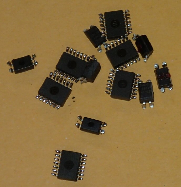
I replaced all the PC928s and their related over-current signaling optos and it fixed the problem. Directly after the replacements I reached a screwdriver into the unit and shorted the output of one of the over-current optos as would occur during a perceived severe overload and the drive faulted to the exact same fault we'd been seeing, so this kinda confirms that it was this aspect of the drive and not the current-coil measurements, which I suspect are read much slower for averages and to monitor for motor overload protection etc.

So, no not scrapped but repaired!


Keith Cress
kcress -
 

Ok, Thank you. Food for thought, we have a DC drive tripping out on over current fault it's sporadic and may need to be addressed if it gets worse so I'll keep that in mind.

Chuck
 
The re-placed:
P5080106_hgrwfu.jpg


Keith Cress
kcress -
 
Mike and Keith - my heroes! PLS for both of you. This is good!

Gunnar Englund
--------------------------------------
Half full - Half empty? I don't mind. It's what in it that counts.
 
Thanks Gunnar!

And Mike, about your cooked solder joints, I've seen that a lot. Essentially any part that you cannot leave your finger on will suffer premature joint failure given enough time. I think the solder literally evaporates over time. To fix it I either find a larger part like using a 5W resistor in place of the cooking 1W resistor or I stand a replacement on its full length leads by wrapping the leads around something to put little pig-tails in them so the resistor's heat has to travel much farther to reach the joint and the loops provide more heatsinking to the air.

Keith Cress
kcress -
 
RoHS and lead-free solder is part of the story, in my opinion.

Military is not forced to use lead-free. They need stuff that works.

Gunnar Englund
--------------------------------------
Half full - Half empty? I don't mind. It's what in it that counts.
 
Hold on. You actually replaced components on a surface mount PCB? I thought this was illegal in today's world of "replace the board, we don't have time to fault find". I do hope that the International Union of Board Jockeys don't come across your obvious malfeasance and proceed to have you disbarred.
 
I better lay low huh? Last month we got a quote for a new CPU board running a large CNC machining center; $2,400. I rummaged around the joint and found seven dead CPU boards laying here and there!

I decided to try repairing one. I couldn't fix it. Tried a second and DID fix it. Tried a third and fixed it, a fourth and fixed it, a fifth and fixed it. I stopped there, figuring the machine I got back on-line and three spares would be enough. The last two someone else had tried repairing and failed, I couldn't bear to give them effort seeing what they'd done already. The company that quoted the $2,400 was very disappointed. :)

Keith Cress
kcress -
 
>Tried a second and DID fix it. Tried a third and fixed it, a fourth and fixed it, a fifth and fixed it

bad electrolytic caps?
 
Yes, in all cases, but also several other issues like SMD parts that had just gone away altogether! And, one had a failed 2.5V Vreg. (Didn't help that it was under the frikken glued-on CPU heatsink.)

Each board had about 30 electrolytics that were absolute misery to replace. They were glued on and the 10 layer boards tried to defy all attempts to de-solder the caps. Couldn't get the holes to 'suck' clean either no matter what tactic was employed. Finally resorted to re-drilling or chasing every hole with board fab drills.

Keith Cress
kcress -
 
Very good job Keith! Did you figure out WHICH ONE of those chips was the weak one? :)

Since you enjoy doing this, keep in mind that as dc bus caps age they allow more and more ripple to pass, and this can also be cause of worsening cases of seemingly untrue overcurrent detection faults.

 
Hi Mike! Thanks. Ah yes, al caps are always the most suspect and first thing to look at but in this case there were surprisingly few. Not a single one on the drive board. There were a few on the powersupply board but I didn't go there much this time around.

I did not figure out which one was at fault because they were all ganged and to run the drive the four boards all had to be stacked to operate. The power traveled between boards via screws which rigidly positioned them. This GREATLY restricted access to the pins of interest in the assembled hot stack. I'd have had to solder wirewrap wires to all the SMD pins of interest which would've run the time past all reason instead of just past reason as was the case..

Keith Cress
kcress -
 
Status
Not open for further replies.

Part and Inventory Search

Sponsor