Eng-Tips is the largest engineering community on the Internet

Intelligent Work Forums for Engineering Professionals

VFD High Frequency grounding of stator vs. return path via. power cable tray + PE + bare Cu cable 5

Status
Not open for further replies.

Jensdsds

Electrical
Jun 9, 2021
33
0
0
PL
Hello,

In a MV MW system with a VFD driving a motor, how do you handle grounding the High Frequency common mode currents?
The rotor has shaft grounding which is grounded to the stator frame.
Stator frame is grounded via the PE cable routed in the same cable tray as the power cables. The PE cable is terminated at the noise source, the VFD.

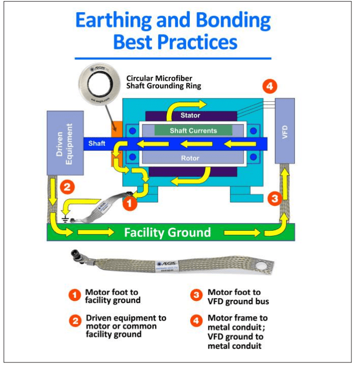
In the Aegis HF grounding strap white paper attached, and in the picture below:
It is recommended to ground the stator frame, driven equipment and VFD using a HF grounding strap.
Sk%C3%A6rmbillede_2022-09-01_094619_pjzo4y.png

My question is:
Would the best return path for HF noise not be the cable tray well connected from stator frame to VFD + PE cable and a bare Cu cable.
Instead of grounding the HF noise to your foundation grounding, where you have no clue about the return path to the VFD creating possible signal cable interference?

I hope you have some insights on this, please reach out if i need to explain myself further.
Kind regards - Jens.
 
Replies continue below

Recommended for you

The entire point is to close the high frequency loop between, specifically, the VFD and the motor chassis with the absolutely lowest high frequency return path possible. Keeping this mash-up of high freq noise out of everything else as much as possible would preclude deliberately running it thru a facility's metal where it will seek to return to the VFD thru undefined paths.

Because of skin-effect high freq energy doesn't travel thru conductors it travels above them, "above their skin". Naturally the more the "skin" the lower the impedance for this current.

The ideal return path is as large a conductive surface as possible, as short a distance as possible between the motor chassis and the VFD's chassis. This would be either a LARGE diameter conductor, multiple conductors, or Litz wire. The most common would be to use regular cable as large as reasonable. Even if other grounds exist to, say, the facility grounding network a low impedance direct ground as describe will shunt all the high freq directly back to the VFD preventing it from causing problems elsewhere.

Keith Cress
kcress -
 
Thank you for your answer,
So you common thing to do is to trust that the PE cable (1/2 size of the power cables, approximately 150mm2) would function as a sufficient return path?
I'am guessing that a well connected and terminated cable tray also adds to this functionality.
 
The lowest impedance HF path would be the shield on shielded power cable - link to southwires version I have not seen any actual installation of this product.

It will work almost as well to put the wire in metal conduit, as long an all of the joints are made up tight, and any sections made with spiral strap (most flex) are bypassed. Spiral strap acts like an inductor at HF.

If HF is allowed to randomly enter the plants grounding grid, there is a good chance the grounding grid will radiate the HF and interfere with wireless transmissions.
 
Thank you for your answer FacEngrPE.

The use of shielded cables is still up for debate, as the pricing increase by almost 50%. But ofc. it is the preferred option.
Also i find it hard to argue for shielded cables seeing as it's difficult to predict/calculate the need for it before system operation.
But it is good to hear your knowledge. I think controlling the return path through the cable ladder system is the correct way.
 
So you common thing to do is to trust that the PE cable (1/2 size of the power cables, approximately 150mm2) would function as a sufficient return path?

No. I would use full size ground wires not 50% PE because you want that surface area not because you need more fault current. You're sizing the wire larger for something else.

Keith Cress
kcress -
 
Jensdsds One good way to look at "selling" management on the higher cost of shielded cable is this: what's the price for premature failure of the motor(s) - not just the ones connected to the drives, but ALL of them connected to the distribution system in the plant? How about the failure of every UPS connected to the same distribution system? How about the premature failure (or at least intermittent errors and faults) of every piece of electronic gear connected to the distribution system? And how about the cost associated with having to go back and tear out the wrong cable and re-pull the correct shielded stuff?

As itsmoked mentioned - use the LARGEST SURFACE AREA ground conductor with the LOWEST IMPEDANCE (not just resistance) you can afford. The skin effect is the important thing for high-frequency signals, so the surface area is what drives the conductor size. For very large, very critical machinery it is not uncommon to have the cross-section of the grounding conductor AT LEAST the same as the main power conductor (for a single phase) - and sometimes the next size up. Remember to keep the run as short as you possibly can.

If you're going to operate a motor on a drive, or use a drive as a frequency changer somewhere in the system, the need for shielded cable ALWAYS exists. (We've learned a thing or two since the early drive days of the 1970s and 1980s. Why do you think aerospace uses shielded cable for everything in the aircraft?) Think about it this way - the cable manufacturers wouldn't be jumping through all the hoops to make the stuff if there wasn't a need for it.

Note that several IEEE and IEC standards exist on this topic - ranging from the drives and how they should be grounded/connected to the motor, to how to select and/or terminate the cables themselves.

Converting energy to motion for more than half a century
 
Thank you for your answer Gr8blu!
Some very good points.
I feel that I have a good understanding of the best practices in this topic.

The thing I'm wondering though is, if you fulfill all of the best practices will it ever be too big of an overkill.
Shielded cables, PE cable one size larger than the power cables, well terminated and connected cable tray including bare cu wire.

It is a hard topic to predict what is too much and what is too little, so ofc. we go for too much.
 
Yes it is hard to predict. Likely impossible because of the things around the motor/VFD. Some are poorly designed, some are just naturally sensitive. All this mashup is not predictable so the conservative thing to do is always go overboard on what you'd have to do to remedy the problems that could show up. Life's too short for people and companies to do the minimum then when completely vexing production stopping issues show up trying to troubleshoot the problem while production suffers and engineers waste hours.

I always ground the motor directly back to the VFD on its own isolated ground if possible AND to it's own VFD ground screw.(lots have two) Then I ground the VFD to the PE system from a different VFD ground screw. That way the high freq noise is greatly discouraged from ever going back out to the network grounding. I'd ground the "cable ladder system" but certainly not to the motor.

For entirely different reasons I also always include a reactor in the power to the VFD. The last thing I want is to cause facility issues with harmonic distortion.

Following these two tenants I've done dozens of complex control panels containing, sometimes, multiple VFDs, PLCs and lots of 24vdc inputs, and analog inputs and avoided ever having VFD related issues.

The grounding is a star pattern with the VFD one leg of the star and the motor ultimately grounded directly to the VFD.

Keith Cress
kcress -
 
Thank you Keith for your answer, very informative indeed!

When describing the "Own VFD ground screw" Do you mean the "power ground" which it is often named by VFD suppliers?

Shouldn't the cable ladder also be grounded to the "Power ground" to offload the HF freq. noise induced in the metal during the cable run?
I'm guessing that the large metal area of the ladder/tray functions as a relatively good HF conductor.


The ladder should be grounded but not to the motor via the motor nor closing a loop with the motor.

Here's a typical VFD. Note a lot of them them have 2 ground screws. One would go only to the motor. The other gets connected to the local PE ground that's grounding everything. That means all the HF that's trying to get back to the power stage of the VFD has made it back. For it to leave into the facility PE network it would have to cross the VFD body and leave via the star ground.

If your VFD fails to include a second ground then you're stuck with using a single connection but by all means continue with the described topology. Bring the motor ground and the network grounds there separately.

VFD_Power_w0ntxz.jpg


While the ladder might seem like a good HF ground path it will be radiating noise everywhere and coupling the noise into all the cables on the ladder. That's not a step in the right direction.


Keith Cress
kcress -
 
Thank you for your answer!

Will a HF noise circuit loop not be created if the ladders are grounded to building PE only?

From converter - through the power cable - Induced onto the conductive cable ladder - trough ladder grounding wire - to building ground system - back to the converter PE.

Please correct me if I have the electrical physics wrong here.
 
Status
Not open for further replies.
Back
Top