Continue to Site

Eng-Tips is the largest engineering community on the Internet

Intelligent Work Forums for Engineering Professionals

  • Congratulations IDS on being selected by the Eng-Tips community for having the most helpful posts in the forums last week. Way to Go!

VFD input current

Status
Not open for further replies.

itsmoked

Electrical
Feb 18, 2005
19,114
Installed a VFD into 240V open delta with a stinger running 222V.

Powered it up, set all the parameters.

Turned on the motor everything was working.

For the heck of it I clamped an ammeter around each supply phase.

With no load on the motor:
L1 was 3.7A
L2 was 3.7A
L3 was 0.0A

The stinger is on L1.

Why does one phase have no current?


Keith Cress
kcress -
 
Replies continue below

Recommended for you

If one leg of the delta is low then it may never conduct, the supply imbalance is causing the input to behave behaving like a single-phase rectifier across the two lines with the higher voltage
 
Lovely..
From my 4AM memory
L1 to neutral was 222.2
L2 to neutral was 124.7
L3 to neutral was 124.9

L2 and L3 could be reversed above.


Keith Cress
kcress -
 
Current is drawn by the rectifier to satisfy the demand of charging and re-charging the capacitors. With no draw out of the capacitors through the inverter, you are only looking at the SR of the capacitors and the PCB power draw as "load". So to ScottyUK's point, there is really next to no demand for power flow out of the caps, so if the first two pulses from the diode bridge satisfy what little demand there is, then no contribution is required from the lowest phase. Turn the motor on and you will see more current drawn. In addition, some VFD designs derive power for the PCB from an AC/DC power supply connected to two of the input phases, vs using a DC/DC chopper off of the DC bus.


" We are all here on earth to help others; what on earth the others are here for I don't know." -- W. H. Auden
 
The voltages of interest are phase to phase, not phase to neutral.
The voltages out of an open delta can be very well balanced, but not always.
With a firm supply and balanced voltages to the transformers the output voltages may be very well balanced.
Where the problems come in and where the open delta gets a bad reputation is where there is a voltage drop on the primary conductors.
The supply neutral conductor is often a lessor gauge than the hot conductors.
With the wye/open delta, the primary neutral conductor may carry more current than the primary hot conductors.
Combine more current with a smaller conductor on the neutral and you get a voltage drop and a neutral shift, and phase angle errors.
Be that as it may, there are many open delta systems in service with little or no issues.
I'm guessing that there is a load on the open delta bank.
I'm also guessing that the VFD is the only load that is voltage balance sensitive enough to show a problem.
The big question and the question that may force action to be taken is:
When the motor is drawing rated current, are the input currents into the VFD acceptable?

Bill
--------------------
"Why not the best?"
Jimmy Carter
 
This was with the motor running, the infamous saw. There was no load since it wasn't cutting. There was no way for me to actually load it other than accelerating it.

Long story short today before ever cutting a single piece of metal they shorted the +DC bus to ground destroying the VFD I finished installing at 4AM. Another is on the way. As my son pointed out it wasn't even a proper single-use. LOL

Keith Cress
kcress -
 
With that small a VFD, I'm surprised you had 3.7A of current when running the motor with no load.

A reactor would help balance the phase currents.
 
Any three phase induction motors running across the line will tend to balance the voltages. The amount of effect will depend on the relative size of the motor(s) running compared to the size of the open delta bank.

Bill
--------------------
"Why not the best?"
Jimmy Carter
 
So, I received an identical replacement drive next-day today, installed it right back into the same spot. Due to the critical and now down-for-a-week production line I spent extra time checking and rechecking all the wiring. I ohm'd out everything twice. No shorts to ground, rational stator values across the motor leads, brake resistor had exactly the right resistance and no continuity to ground. Everything looked fine.

I went over to the 200A panel and standing as far to the side as possible turned on the 40A breaker feeding the VFD. KABOOOOOOM! Lights out! Entire production facility down. It didn't trip the panel 200A breaker but it did trip the breaker in my hand and the service drop 200A breaker out where the underground service enters. I turned OFF the tripped 40A breaker and turned on the service entrance 200A and everything came back on. On returning to the VFD black stink soot had shot out every last vent slot and even out of the tight case seams.

They thought they'd have their production back up by tomorrow. Dang.
2qu5d3o.gif


Now I have to find a 240V 3ph 5.5kW/7.5hp drive in Silicon Valley tomorrow somewhere and try to get them back up by Monday. I will NOT be trying anymore WEG drives. I know Jeff... You're muttering "see!" right now.

Do you have any SV suggestions for where I could get a drive tomorrow (Friday) Jeff?

Keith Cress
kcress -
 
Does this drive have a connected neutral?
Does this drive have internal over-voltage suppression that may be choking on the wild leg?
Strange that it ran for a year. I wonder if the utility pushed the supply voltage up a few Volts recently.
Possibly something smoked the first time that it was connected and took out one phase.
It may have been running on two phases for a year on the short duty cycle.
I would be installing a delta/wye isolation transformer ahead of any replacement to avoid sending the wild leg into the VFD.
Is DOL an option until you can locate replacements?

Bill
--------------------
"Why not the best?"
Jimmy Carter
 
I think waross hit it on nail head.
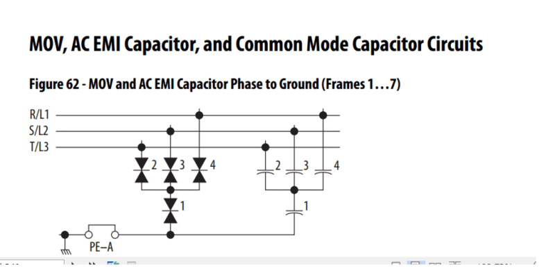
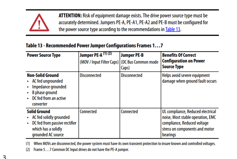
There is probably that link where needs to be disconnect for a delta config on the VFD.

Its usually some MOV to ground that is usually a screw bolt that needs taken out on install.

This happened to me in past was a painful memory.

This is just an example not sure what your documentation looks like for your drive

ComModeCapJumper_riujyx.png

ComModeCapJumpertable_phshpb.png
 
Bill; No neutral anywhere. I think you're missing the recent history.

Schnider drive ran for a year and died.

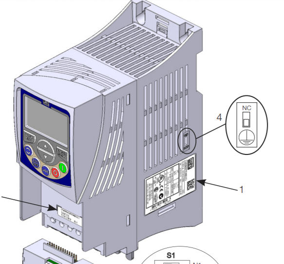
Put in a WEG CFW500C24P0T2DB20 CFW Manual
Ran fine for me setting it up. Powered it up/down about 5 times.

Customer shorted DC bus + to earth ground. This blew every single drop of magic smoke out of the power driver puck.

Installed an exact replacement again.

On first power up Kawblewie!

-----------------------------------------

controlsdude; Thanks for the picture. Makes sense. However this drive has no neutral connection to it. It does say on page 16
ATTENTION!
The power supply that feeds the inverter must have a grounded neutral. In case
of IT networks, follow the instructions described in Item 3.2.3.3 IT Networks
on page 17

Which it does since the panel is supplying single phase loads around the facility. There is no neutral connection to the drive. I took their point to mean they didn't want unconstrained earth potentials available and having the panel neutral does this.


Keith Cress
kcress -
 
Nope! Not it.
I just looked at the carcass and there is no internal filter and the switch opening has nothing behind it. No switch installed.

Keith Cress
kcress -
 
Status
Not open for further replies.

Part and Inventory Search

Sponsor