Guilhermebr
Electrical
Hello
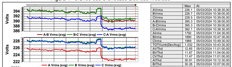
I made some measurement in 3 phase 60Hz 380V, in the input with 3 VFD 500CV same bus.
Below waveforms voltage e current at max load, and resonance probability? maybe between capacitor DC Voltage bus x grid AC cables?
The is 250 metes low voltage cables, betwenn suplly transformes and input AC VFDs.
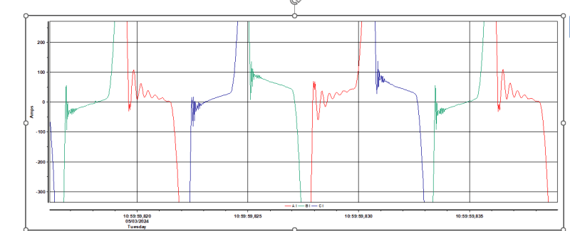
current_oscillations_around_zero
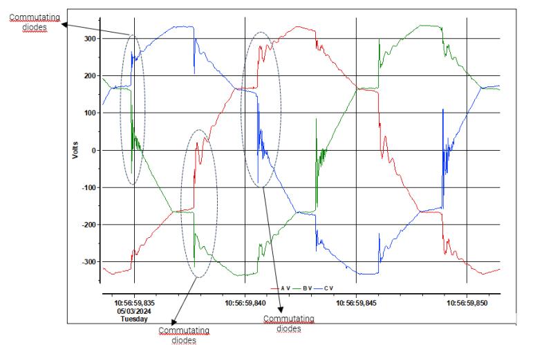
voltage_commutation_diodes
GS
I made some measurement in 3 phase 60Hz 380V, in the input with 3 VFD 500CV same bus.
Below waveforms voltage e current at max load, and resonance probability? maybe between capacitor DC Voltage bus x grid AC cables?
The is 250 metes low voltage cables, betwenn suplly transformes and input AC VFDs.
current_oscillations_around_zero
voltage_commutation_diodes
GS