Continue to Site

Eng-Tips is the largest engineering community on the Internet

Intelligent Work Forums for Engineering Professionals

  • Congratulations KootK on being selected by the Eng-Tips community for having the most helpful posts in the forums last week. Way to Go!

Vibration Analysis

Status
Not open for further replies.

pcexpertsahil

Student
Aug 17, 2023
4
My Experimental and Simulation modal frequencies are not matching , Assuming my Simulation is correctly done is ansys what to do in order to match ?? the difference is more than 100hz between simulation and actual. is it necessary to add a virtual weight or load to disc in simulation in order to match ?? Please help
My Component is a symmetric disc . I have performed analysis on vanes or baldes before and there it was always very close to simulation results atlest for first 3 modes. But now it is not matching at all .
 
Replies continue below

Recommended for you

I am currently doing a college project in which I have to find the natural frequency of a disc of about 250mm in diameter ( axis symmetric disc). For doing this I mounted this disc to an electrodynamic shaker and had done a frequency sweep from 5hz to 500hz.
I have attached 4 strain gauges to the component and 2 accelerometers to the fixture. Around 250 hz I am getting a sudden rise in strain data reading ( A peak) also there is a loud sound for 2 seconds.

I have also performed Modal Analysis Simulation in Ansys and have found the first 3 modes at 1) 150.11 2) 150.88 3)260hz
Experimental analysis revealed the first mode at 250hz but the simulation says 150hz, there is a 100hz of difference which is huge.

Q1) Do I have to give any pre-stress condition in simulation so that the value will match? If yes how? I have tried static structural analysis results giving input to the setup of the modal and I tried giving outward pointing remote forces at an equidistant location 15mm away from the disc but it didn't help.

Q2) In the simulation the difference between the first two modes around 0.7hz can it be true in reality ? the mode shape is transverse in nature with 2 nodes and 2 antinodes all being diametrically opposite respectively and the second mode is also same transverse vibration with 90-degree phase shift but the third mode is symmetric axial in nature.

Q3) for mode shape visualisation I have a stroboscope but since I am performing a frequency sweep I have to continuously change the flashing pulse rate by rotating the dial on stroboscpe so it becomes very tricky and the resonance time frame is soo short that I am not able to tune it into right flashing frequency (rpm) . How to pre-set the flashing rate so that it will correspond to 150 and then 250 hz for second mode ?

Please feel free to share your thoughts .
 
Your experimental setup may be wrong. Where is the shaker attached to the disc? How is the shaker supported? Is this your first time doing an experimental modal analysis? Can you plot the mode shapes for FEA and test?

Cheers

Greg Locock


New here? Try reading these, they might help FAQ731-376
 
Q3, depends on the strobe, the ones we used were triggered off the excitation signal and had a delta f knob. You don't have to use a sine sweep, just use a constant frequency excitiation.

Cheers

Greg Locock


New here? Try reading these, they might help FAQ731-376
 
would help to have photos of the test setup and the FEM mode shapes

the difference is likely due to differences in boundary conditions between the test setup and the simulation. if you have assumed a rigid support in the simulation, well, there is no such thing in reality.
 
There are often uncertainties in:
> device under test (DUT) material or configuration
> test fixture material or configuration
> misuse of misconfiguration of the vibration table.

We once tested a DUT and found a 35 Hz resonance in the test fixture; luckily that was actually spotted by an experienced engineer who could tell there was going to be a resonance from a Powerpoint cartoon of the fixture. In another case, we found a 30-Hz resonance that turned out to the the slip table itself, because the DUT was top-heavy and was rocking the table on the oil film.

TTFN (ta ta for now)
I can do absolutely anything. I'm an expert! faq731-376 forum1529 Entire Forum list
 
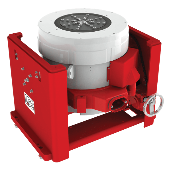
electrodynamic_shaker_ea7u46.png

On top of this shaker the fixture is attached onto which disc is attached
 
the heavily meshed part is the disc , bottom fixture and vertical shaft fused as one component , over which disc is put and on top a plate over which the bolt is attached. There is quite a bit clearance in bottom part of disc . I have even put one bolt under the disc to raise the height but same results were obtained .
 
So not wanting to say I told you so but you have suppressed all modes that have zero displacement at the centre, ie a large number of modes. You cannot excite a modeshape where it is has zero displacement (nodal in the jargon).

Cheers

Greg Locock


New here? Try reading these, they might help FAQ731-376
 
Status
Not open for further replies.

Part and Inventory Search

Sponsor