Hello,
This is the first time I design a fixture for a vibration test, so I guess my question might be basic to most of you.
I have an assembly that should be carried by a certain platform.
The Vibration Spectrum of the carrying platform was measured and is given as part of the requirements.
As part of the assembly design an engineer who is specialized in dynamic analysis made sure that the natural frequencies of the assembly are far enough (higher) and out of the input spectrum.
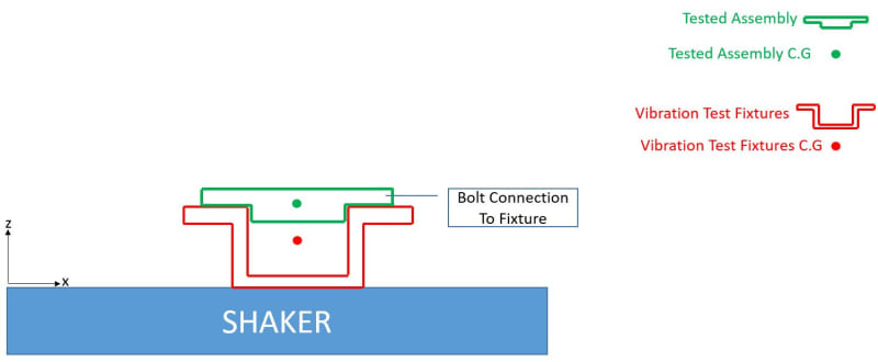
Now I have to plan a vibration test, and shake the assembly through a fixture that is connected to the shaker table. I am attaching a schematic description of the test:
I read that the guideline of fixtures design is making them as light and stiff as possible for achieving a natural frequency as high as possible, so no resonance may occur in the test due to the fixture.
Now I wonder how should I check by analysis the fixture I design.
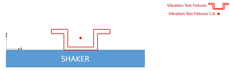
I initially thought that if we have a separate analysis of the tested assembly we only have to check separately the test fixture alone (and make sure its natural frequency is high enough) as described below:
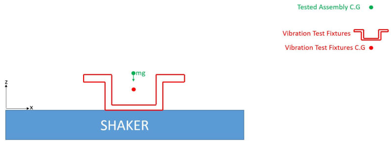
But I was told that this isn't right and that I have to include the Tested Assembly mass in its C.G without taking into account its stiffness etc. as described below:
Remark: I am sure that the most accurate way is an analysis of the entire assembly, but I would like to know what is the right way of design when you don't have an access to the tested assembly, and there is a necessity to simplify.
I will be happy if you refer me to a simplified example in which there is a calculation that illustrate the importance of each factor in the calculation.
Thank you
This is the first time I design a fixture for a vibration test, so I guess my question might be basic to most of you.
I have an assembly that should be carried by a certain platform.
The Vibration Spectrum of the carrying platform was measured and is given as part of the requirements.
As part of the assembly design an engineer who is specialized in dynamic analysis made sure that the natural frequencies of the assembly are far enough (higher) and out of the input spectrum.
Now I have to plan a vibration test, and shake the assembly through a fixture that is connected to the shaker table. I am attaching a schematic description of the test:
I read that the guideline of fixtures design is making them as light and stiff as possible for achieving a natural frequency as high as possible, so no resonance may occur in the test due to the fixture.
Now I wonder how should I check by analysis the fixture I design.
I initially thought that if we have a separate analysis of the tested assembly we only have to check separately the test fixture alone (and make sure its natural frequency is high enough) as described below:
But I was told that this isn't right and that I have to include the Tested Assembly mass in its C.G without taking into account its stiffness etc. as described below:
Remark: I am sure that the most accurate way is an analysis of the entire assembly, but I would like to know what is the right way of design when you don't have an access to the tested assembly, and there is a necessity to simplify.
I will be happy if you refer me to a simplified example in which there is a calculation that illustrate the importance of each factor in the calculation.
Thank you
