Eng-Tips is the largest engineering community on the Internet

Intelligent Work Forums for Engineering Professionals

VNA RFID design problem

Status
Not open for further replies.

Atarek

Electrical
Apr 16, 2017
27
0
0
EG
Hello everyone,

I recently start developing an RFID circuit MFRC522 IC, following the NXP application note AN 1445,
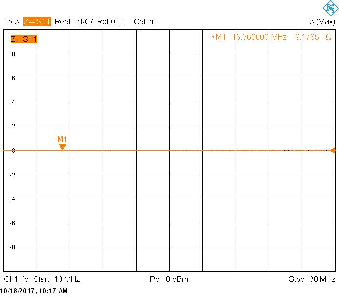
When i try to get the series equivalent of the antenna coil using the VNA, i get a very noisy reading when i try to read the real part of the impedance S11,
it varies from 6 to 10 Ω, see attchment
and when i try to measure the imaginary part, the reading is very stable

Can someone please explain this, (Note this is my first time to use VNA)
Thanks in advance,
ATarek
 
 http://files.engineering.com/getfile.aspx?folder=0b6de277-c48d-4fb3-b40f-93b422be2e9f&file=302E_REAL.jpg
Replies continue below

Recommended for you

For ease of reference:

302E_REAL_uswbu8.jpg
 
AN1445 Section 4.1.1 states that the typical values for the loop 'antenna' are:
L[sub]a[/sub] = 0.3 - 3µH
C[sub]a[/sub] = 3 - 30 pF
R[sub]a[/sub] = 0.3 - 8Ω

It can be a bit tricky to measure low values, unless the equipment is specifically intended for that range. Reliable measurements often demand an order of magnitude more resolution and accuracy than the reading (i.e. an extra digit).

Also, being a coil, it can be more susceptible to picking up ambient noise. So beware of that.

We've used the R&S FSH-3 (for example), and I wouldn't particularly trust that relatively inexpensive model to provide overly-precise measurements at low values. I've seen some evidence of quantitization errors on some readings.

Depending on the nature of the project, sometimes it can be worthwhile to skip over an overly-fussy measurement step, and leave the testing to the 'next higher assembly'. In this case, the final antenna assembly including the matching circuit. That decision depends on the nature of the project.

 
Status
Not open for further replies.
Back
Top