Continue to Site

Eng-Tips is the largest engineering community on the Internet

Intelligent Work Forums for Engineering Professionals

  • Congratulations MintJulep on being selected by the Eng-Tips community for having the most helpful posts in the forums last week. Way to Go!

Voltage Collapse from closed tie 1

Status
Not open for further replies.

Mbrooke

Electrical
Nov 12, 2012
2,546
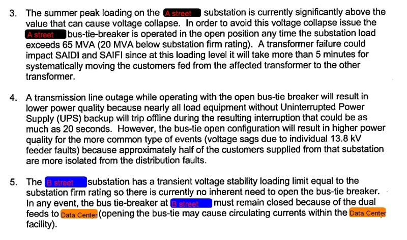
I can't wrap my head around this one... Why would operating secondaries in parallel create a voltage collapse risk for loss of a transmission source? PSS/E is telling me nothing. In my mind the lower Z at the 13.8kv bus would decrease the probability.


Substation_MTM_zgnzjk.jpg
 
Replies continue below

Recommended for you

The way I'm reading it, "voltage collapse" seems a bit overstated; in "my" utility we would likely choose to describe the concern as one of excessive voltage decline. Semantics? I don't think so...

The way I'm reading 3 and 4, with two sources in parallel and acceptable voltage prevailing, on loss of one source there will be excessive voltage decline to all loads supplied by the station.

If instead the station is run with the bus tie breaker open, on first contingency that portion of the load on the affected supply will simply be interrupted; and even though that's not a good thing, "no voltage is better than low voltage," as one of my senior and now retired colleagues used to say.

I find #5 fairly straightforward in saying that it's okay to split at the customer's site whenever desired, but if the station bus tie breaker is to be opened the customer's tie breaker must be opened first so the buses aren't still paralleled via the feeders, as this could cause severe problems for both the utility and its supplied customers during contingencies. Indeed in many situations where our customers have such supply tie breakers that run normally closed, opening of the bus tie breaker at the station sends transfer trip to that customer's tie breaker as well to preclude getting into that situation at all.

Hope this helps.

CR

"As iron sharpens iron, so one person sharpens another." [Proverbs 27:17, NIV]
 
It helps- its comforting to know that I am not the only one who reads it that way.
 
I could see doubling the impedance to a fixed load leading to voltage collapse. Shedding load as a result of the topology configuration would help with both true voltage collapse and with an unacceptably low short term steady state voltage to customers until other system adjustments can be made. The article could also be referencing Fault-Induced Delayed Voltage Recovery (FIDVR).
 
Looked into this further and was able to obtain more info- the substation permissible loading is 85MVA and the nameplate of both transformers is 36/48/60MVA at 14% Z. Voltage dips below 90% (12.42kv) when loaded above 65MVA- so 65MVA is considered the stability limit.


From what I am hearing the idea is that if you lose one of the 60MVA transformers, the remaining unit will be overloaded until a mobile or replacement is brought in. The 5% life degradation is considered acceptable on the basis that unanticipated failures are rare and when they do happen are short lived due to the availability of vagabond units and the ability to manually transfer distribution load to other substations.


For comparison the B street substation has a permissible loadability of 77MVA, a stability loading of 75 MVA, 30/40/50MVA rating and a 12% Z, which would explain why the stability limit is higher despite the lower MVA.

There is another station that has a 99.6MVA loadability rating, a voltage stability of 65MVA and a trafo nameplate of 42/56/70.


In order for any of these stations be loaded above the stability limit, the tap changers must be increased before picking up load.

Very interesting stuff- up until now I had not considered this.
 
Status
Not open for further replies.

Part and Inventory Search

Sponsor