Continue to Site

Eng-Tips is the largest engineering community on the Internet

Intelligent Work Forums for Engineering Professionals

  • Congratulations MintJulep on being selected by the Eng-Tips community for having the most helpful posts in the forums last week. Way to Go!

Voltage Drop Calculation 8

Status
Not open for further replies.

PoliPoliCarps

Electrical
Nov 9, 2018
35
Hello.

I computed my system
From 3.3kV/400V IT System, 50Hz,
Length is 100 mts from Transformer to Main CB of LV Switchgear
Length is 50 mts from Protection Devices to Motor Loads
It calculates the voltage drop but is too high around 17%
Requirement Voltage drop should be atleast 10% only.
I used EPR type of Cable for Mining

Please help me reduce voltage drop

Thank you

 
 https://files.engineering.com/getfile.aspx?folder=a7784a30-bdb6-4819-97b8-d39a58a972ae&file=voltage_drop_problem.png
Replies continue below

Recommended for you

Add parallel conductors.
Use a soft starter.
Use a VFD.
Use wye/delta starting. NOT recommended. This will give poorer performance but better numbers with a simple voltage drop calculation. A realistic voltage drop calculation that considers the transient current at the instant of transition from wye to delta will probably give a much worse calculated voltage drop.
Move the motor closer to the supply or otherwise shorten the cables.

Bill
--------------------
"Why not the best?"
Jimmy Carter
 
The length you have 100m and 50m is considered as standard length which should also have a standard size of cable/conductor that means you have a standard cable gland as well (do not need any change box in between or reducer for cable termination). So, there will be no any problems to increase cable size to next higher size or add another cable (parallel conductor) as Bill suggest above.

Using Soft starter and VFD is depends your applications or process requirement that you have to check with Process or Operations guys. Both may be not suit to your application!
 
Mr. ElecEE8,

Yes. I cannot change the 100m and 50m since that is the length to the equipment since this is mining.
I tried using the parallel conductors it has not much effect on the voltage drop
from 17% down to 15%. I use 2-runs of 185 sq.mm

About the VSD, yes when I tried it in the calculation VSD was able to eliminates the voltage drop but I check with the process or application, the Process is Crushing Unit / Crusher Unit which I think the use of VSD is not advisable VSD may trip from time to time with this type of operation and does not really suit the application.
 
I saw your SLD attached. Below is my suggestion;
1- To compensate voltage drop in this case, you can raise the tap of transformer (off circuit tap changer) to increase voltage on secondary side e.g. +5% means you will have ~420V at secondary side and at switchgear bus bar you may have 415-420V almost.
2- If you are going to have new transformer, you need to specify it to 3.3/0.433kV (not 3.3/0.4kV)
3- If still not resolve, and it is new installation then you may consider 3.3kV motor for both motors instead of LV motor (400V). The motor rating you have is a little bit big to connect on LV system (normally motor cut off rating is 132kW and above shall be 3.3 or 6.6kV motor). Another small motor you can mange it with other LV switchgear nearby..

Hope it helps.
 
I don't think you care about the voltage drop but the voltage received by the equipment. Maybe, you run the system high to offset the drop to the equipment? Some plants intentionally run their systems high so that their weak feeds have acceptable voltage.

Put capacitor banks near your equipment?

Using cabling that bundles all three phases together or managing the spacing between the phases.


------------------------------------------------------------------------------------------
If you can't explain it to a six year old, you don't understand it yourself.
 
I like the tap solutions posted by others. I never liked EPR for severe-duty operations, especially where wet, personnel, salt, etc. XLPE would be my first choice and I'd run multiple conductors/phase of 500 MCM or greater - perhaps THOF-500 or equivalent if you want some flexibility. Swapping out the cables may be your cheapest option if the tap changing solutions proposed do not sufficiently help.
 
Back to basics: What is the basis for the 10% maximum voltage drop while starting? These requirements are often entirely arbitrary. What is the size of the motor?

If the voltage drop is the primary concern, the soft starter should solve that. But acceleration time and starting torque will decrease. If trying to start motor with a loaded crusher, the real concern may be having adequate torque to accelerate the crusher without stalling.

The voltage drop is primarily in your transformer. So make sure you have the correct transformer size and impedance. A larger transformer would definitely help.

Talk with the mechanical engineers.
 
dpc beat me to it. Voltage drop calculations are generally applied to rated currents.
The voltage "DIP" limit during a starting surge is often a matter of judgement.
At times we are faced with an arbitrary limit on voltage dip.
Yes, there is a point where the voltage dip becomes unacceptable, but more often it is a matter of compromise.
If the voltage dip is primarily in the transformer, you may not be able to meet your limit with any amount of parallel cables.
Solutions:
A soft starter. This may not be a viable solution for your application.
Higher transformer taps. Investigate as to whether your supply has a history of higher voltage excursions which may push the voltage unacceptably high.
Cost out the options and reevaluate the arbitrary voltage dip limit.
There may be a good reason for the limit but more often you can live with a greater voltage dip.
It looks as if the transformer is 100% loaded. Some codes limit the maximum continuous load on a transformer to 80%.
I doubt that you will be able to start one of those motors on the 630 Amp breaker.
With one motor running and loaded, forget about starting the second motor on that breaker.
Consider a larger transformer.


Bill
--------------------
"Why not the best?"
Jimmy Carter
 
If the rated voltage at transformer terminals has to be 400 V at full rated power [S=400 kVA] the no-load transformer voltage has to be 417 V[at least].
[for an IEC standard transformer the rated low voltage is the no-load voltage. It could be 420 V here].
Increasing no.of parallel cables will not reduce enough the voltage drop from transformer to 400 V switchgear busbar, since the voltage drop across the transformer is elevated at motor starting[13.8%].
A rule of a thumb is: the transformer power [apparent power kVA] has to be at least 3 times the motor rated power. In your case Stransformer=3*160=480 kVA in case the induction motor starts D.O.L.
So you have to reduce the motor starting current at maximum 4.5 times the rated[delta-star start at least].
At 4.5 times the Switchgear busbar voltage will be 364 V [91% of 400 V rated] and the voltage at motor terminal will be 352 V[12% drop].This will meet IEC 60038 and IEC 60034-1.


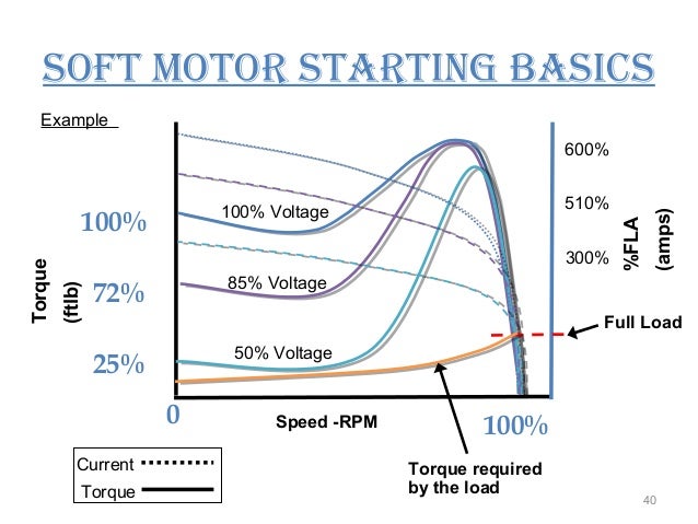
I think one think to bare in mind is that Waross's is addressing issues related to voltage drop during motor starting. Some of the others are offering solutions for the voltage drop during normal operation. Raising the voltage exasperates motor inrush during starting. Softstarts, VFDs, and alternative transformer windings reduce the inrush by starting the motor at a lower voltage. There is a page in the IEEE Red Book that will give you an estimate of how voltage affects starting current.
starter-of-an-induction-motor-40-638.jpg


------------------------------------------------------------------------------------------
If you can't explain it to a six year old, you don't understand it yourself.
 
As a Utility guy, I always worry about impacts to other loads.

Have you looked at the drop/flicker effects to the rest of the facility? You may have to consider other more sensitive loads on the source side of your transformer. In extreme cases, the Power Utility may specify a maximum flicker on THEIR side of the main transformer as well.
 
Additional, for tap changer adjustment solution.
If you want to try on this. I would suggest to run the load flow to optimize the tap position.
You need to run min. and max. voltage cases to find the optimized position of the tap changer to avoid affected undervoltage & overvoltage to others equipment.
Min. voltage case - maximum load flow case
Max. voltage case - minimum (light load condition) load flow

From LF results you will see all buses & terminals voltage..

The Gunner/EE8
 
The impedance of the total circuit is based on the total resistance of the various components such as transformer windings, cables and loads combined with the total reactance of the various components.
Any calculation based on the KVA of the various components is an approximation.
Any calculation based on the KVA of the various components is accurate only when the X/R ratio of all the components is equal.
Try this:
Voltage drop = impedance times current where the impedance may be expressed as
Ohms impedance = √(R transformer + R cables + R load)2 + (X transformer + X cables + X load)2

Bill
--------------------
"Why not the best?"
Jimmy Carter
 
Waross hinted at this but the power factor of the current drawn will impact your voltage drop. The full calculation will be VLoad = Vsource - vector(current to the load)*vector(sum of impedance to the load). Your cables will have a lower X/R ratio so it won't make as much of a difference on those. Your transformer due to it being very inductive will have a voltage drop that varies with the power factor. A poor lagging power factor load will create a larger voltage drop on the transformer than a good load with pf closer to 1.0.

------------------------------------------------------------------------------------------
If you can't explain it to a six year old, you don't understand it yourself.
 
Hi PoliPoliCarps
I have attached a useful spreadsheet for sizing transformers for starting large drives refer transformer secondary terminals
VD. I guess from the amps that the large drive is 185kW and it would appear that the base load is larger
than the Transformer kVA rating.
 
 https://files.engineering.com/getfile.aspx?folder=00676911-2856-4ab3-852d-97dc1925e0dc&file=Transformer_Regulation_(002).xls
Checking Padlock01's figures I see that your transformer is 1.4 Amps over rated current.
I don't generally load a transformer past 80% for motor loads.
Try your numbers again with a 500 KVA transformer.
The voltage drop when staring the last motor will still be over 10% but it may be close enough to be acceptable.
You show motor loads only on that transformer.
If that is the case, then a 500 KVA transformer is good design practice and will give acceptable starting performance.
I personally would resist using a 400 KVA transformer for those loads, even with soft starts.

Bill
--------------------
"Why not the best?"
Jimmy Carter
 
It is a very interesting excel file, indeed.
Still I have some remarks-if I may say that.
At first I think 400 V it is the voltage phase-to-phase at transformer low voltage terminals when the transformer load is full-rated [ 400 kVA].In this case the no-load voltage has to be more[I think 5% more: V=400 V; U=420 V].
If we consider transformer impedance Zk=Rk+jXk and considering Rk=0 then Xk=4%/100*0.4^2/0.4=0.016 ohm.[ According to IEC 60076-1 Tb.1 the tolerance is ± 7.5% that means maximum Xk=(1+7.5/100)*0.016=0.017232 ohm.]
By the way the motor output power has to be 160 kW Pn=sqrt(3)*V*Irat*cos(φ)*eff and if cos(φ)=0.85 and eff=95% Pn=160.6 kW.
The motor locked rotor[starting] current could be up to 8 times rated.
As per IEC 60034-12 Table 2 Sstart=10*Pn=160*10=1600 kVA then Istrat=1600*1000/sqrt(3)/400=2309 A at 400 V.
The motor locked rotor current it is direct proportional with the voltage at its terminals. Then at 20% drop[(1-0.20)*400=320 V the current will be 2309*320/400=1847.2[6.44 times rated].
This current with cos(φ)=0.34 has to be added to the transformer rated after subtracting the rated motor current [we cannot keep both currents in the transformer total current].
The the transformer current at one motor start will be:
Itransf.rated*[0.85-jsqrt(1-0.85^2)]-Imotor.rated[0.85-jsqrt(1-0.85^2)+Imotor.start*(0.34-jsqrt(1-0.34^2)=874.5-j1890.1 or
2083 A<-1.1373 rad=-65.16 degrees.
DV=sqrt(3)*I*(Rk*cos(φ)+Xk*sin(φ)) =sqrt(3)*2083*0.017232*sin(1.1373)=56.42 V
Vatstart=420-56.42=363.58 V.
Actually the voltage drop from rated is 400-363.6=36.42V[9.1%].

 
Dear Mr. padlock01 I am really confuse, I appreciate the excel file also seems interesting but I do not know how to use because in the excel file it is only the largest motor starting considered right? how about when I have multiple large motor starting at the same time will this excel file still be applicable?
 
Status
Not open for further replies.

Part and Inventory Search

Sponsor