Continue to Site

Eng-Tips is the largest engineering community on the Internet

Intelligent Work Forums for Engineering Professionals

  • Congratulations MintJulep on being selected by the Eng-Tips community for having the most helpful posts in the forums last week. Way to Go!

Voltage drop Equation 2

Status
Not open for further replies.

charz

Electrical
Jan 11, 2011
95
1. In voltage drop calculations the Voltage drop equation is IR Cos (phi) + IX Sin (phi). What is phi here?
Phi - Power factor angle of the load
(or)
Phi - Internal Impedance angle of the transformer (arc tan (X/R)) where X/R is the X/R of the transformer.

2. For example, In cable size adequacy check, Phi is the load power factor angle, not the arc tan (X/R) of the cable. Here why not the cable angle is considered?

3. Is voltage drop at full load due to %Z is same as the voltage regulation? what is the difference between as it appears to be the same? How power factor affects the voltage regulation?

 
Replies continue below

Recommended for you

1. PHI is there because the voltage drop across the transformer is a vector. For a purely resistive load, the voltage drop across the transformer will be I*Z. Assuming the transformer is purely reactive, the voltage drop will be 90 degrees out of phase with source voltage, reducing the voltage drop seen by the load. Likewise, with a purely reactive load the voltage vectors will be in phase and the voltage drop will be the most.

2. I am guessing the cables are close enough together that their positive sequence reactance is lower and I think you are being conservative if you just assume the cable voltage drop is inline with the load. Vload = Vsource * (Zload)/(Zload + Zcable). Zload + Zcable is the most when they are in phase
 
Transformer impedance determines the available short circuit current. A look at a typical X:R ratio will indicate that this current is quite reactive.
At normal loading the load impedance is in series with the transformer impedance. With typical loads this is mostly resistive.
Transformer regulation is the voltage drop at full load with a typical power factor.
The Canadian Electrical Code has voltage drop cables that take the reactance of the cables into account.
Bill
--------------------
"Why not the best?"
Jimmy Carter
 
charz said:
1. In voltage drop calculations the Voltage drop equation is IR Cos (phi) + IX Sin (phi). What is phi here?
Phi - Power factor angle of the load
(or)
Phi - Internal Impedance angle of the transformer (arc tan (X/R)) where X/R is the X/R of the transformer.

2. For example, In cable size adequacy check, Phi is the load power factor angle, not the arc tan (X/R) of the cable. Here why not the cable angle is considered?

3. Is voltage drop at full load due to %Z is same as the voltage regulation? what is the difference between as it appears to be the same? How power factor affects the voltage regulation?
1. phi is the power factor angle of the load.
2. Cable angle is considered in the R and X.
3. Voltage regulation is a particular form for expressing voltage drop for a transformer. Regulation is defined as the change in output (secondary) voltage which occurs when the load is
reduced from rated kVA to zero, with the applied (primary) voltage maintained constant and is expressed as a percentage of the full-load secondary voltage.
Reg (pu) = R⋅cos(phi) + X⋅sin(phi) + [X⋅cos(phi) − R⋅sin(phi)]²/2, where R and X are per unit resistance and reactance. Reg % is 100 x Reg (pu).

 
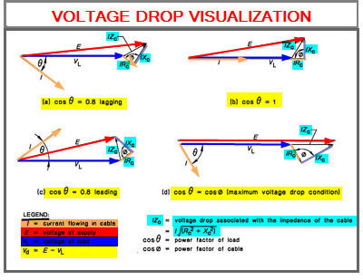
See if the enclosed info could help:


Voltage_Drop_Visualization_vnpcpb.jpg
 
Thank you cuky,

The resistive voltage drop that occurs due to cable resistance is IR Cos (phi) Where Phi is cable impedance angle and the reactance voltage drop that occurs due to the cable reactance is IX cos (phi). My question is why this phi is excluded in the voltage drop equation instead only load power factor angle(theta) is considered. Also, this phi (cable impedance angle) is independent of load.
Does not including cable impedance angle in the voltage drop calculation means it is less accurate?
I'm not questioning the well-established equation but it is rather my inability to understand why only load power factor (theta) is considered and why not also phi?

 
Transformer_voltages_diagram_qzmqko.jpg

If we should measure the power factor at high voltage terminals the R and X of the transformer would be taken into consideration. However, in across transformer voltage drop calculation only load power factor is required.
From the attached sketch the voltage drop will be:
DV=|Vp|-|V's| it is the subtraction from absolute values.
Vp=DVp+DVs+V's=Zp*Ip+Z's*I's+V's
V's=Vload*wp/ws where wp=number of turns of the high voltage and ws=number of turns of the low voltage winding.[ wp/ws=~VHV/VLV transformer rated voltages].
I's=I'load [I'load=Iload*ws/wp] =Iload*[(cos(φ)-jsin(φ)]*Ns/Np Ip=Io+I's Zp=Rp+jXp Z’s=R’s+jX’s
[Since Io depends on Vp in the short-circuit case Vp~0 then Io~0. Zsc=[(Rp+Rs')+j(Xp+Xs')]
However, even in the case Vp=Vrated we may neglect Io as it is less than 3-5%.
An "accurate" calculation taking Io into account will increase the voltage drop by 1.5-2% only.]
So Ip=I's=I'load==Iload*[(cos(φ)-jsin(φ)]*Ns/Np=V's/(R'load+jX'load).Q.E.D.[pipe]
 
Charz said:
Does not including cable impedance angle in the voltage drop calculation means it is less accurate?
Cable impedance angle does not need to be considered because the cable R and X are included. R and X determine the cable impedance angle.
 
Charz,

In my opinion, the associated angles of the power factor of the load and the power factor of the cable are taking in consideration for the voltage drop calculation as follow:

1) The power factor of the load drive the angle of the current with respect voltage at the load.
2) The Voltage drop is also equal to the cable resistive voltage drop (same direction as the current) plus the voltage drop of the cable inductance (90o with respect to the current).


Hope this help.
 
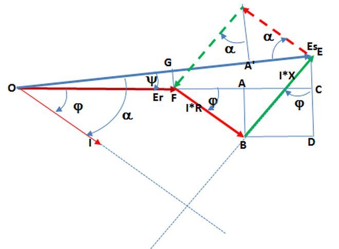
Voltage_drop_Es_and_alpha_v9nkmt.jpg

What it is odd in IEEE 141/1993 formula it is the fact we need to know Es and cos(fi).
Actually you may know Es and cos(alpha)[a] or Er and cos(fi)[ [of the actual load].
In case you know Es and cos(alpha) then:
Er^2=OG^2+FG^2
OG=Es-AE-AG
AE=I*R*cos(a); AG=I*X*sin(a)
FG=I*X*cos(a)-I*R*sin(a)
Er^2=[Es-I*R*cos(a)-I*X*sin(a)]^2+[I*X*cos(a)-I*R*sin(a)]^2
Er=sqrt([Es-I*R*cos(a)-I*X*sin(a)]^2+[I*X*cos(a)-I*R*sin(a)]^2) and VD=Es-Er.
VD=Es-sqrt([Es-I*R*cos(a)-I*X*sin(a)]^2+[I*X*cos(a)-I*R*sin(a)]^2)
In case you know Er and cos(fi) then:
Es=sqrt{[Er+I*R*cos(fi)+I*X*sin(fi)]^2+[I*X*cos(fi)-I*R*sin(fi)]^2} and VD=Es-Er.
In order to get alpha[a] if you know Er and cos(fi) we use the formula:
a=asin((Er*sin(fi)+I*X)/Es)
We get the same VD in both cases.
 
Status
Not open for further replies.

Part and Inventory Search

Sponsor