Continue to Site

Eng-Tips is the largest engineering community on the Internet

Intelligent Work Forums for Engineering Professionals

  • Congratulations Danlap on being selected by the Eng-Tips community for having the most helpful posts in the forums last week. Way to Go!

Voltage given from the secondary of the capacitive voltage transformer 1

Cesme

Electrical
Jan 29, 2019
12
Hello everyone,

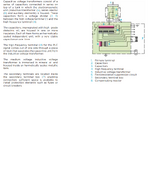
During relay testing, we apply voltage to the secondary of the capacitive voltage transformer (CVT). Some colleagues disconnect the secondary terminals going to the field, believing that high voltage may appear on the primary side during the test. However, I think this is unnecessary.

When voltage is applied in reverse, it will rise up to the inductive part and then be divided according to the capacitance ratio.

How do you approach this in your own systems?
 

Attachments

  • cvt.png
    cvt.png
    332.3 KB · Views: 12
Replies continue below

Recommended for you

If I close the potential ground switch, I will be short-circuiting P1 and P2, which I believe will cause my test equipment to draw excessive current when I apply voltage from the secondary side during testing. Therefore, I think this circuit should remain open during testing. Am I thinking wrong?
 
Last edited:
If you're applying voltage to the CVT secondary, closing the potential ground switch (PGS) will short the intermediate transformer's primary winding and you will get high current in the transformer windings.

To your original question, utility practice comes down to "is there 0% chance" versus "is there little chance". I work for a CVT manufacturer and I can tell you that most utilities that I'm aware of treat the CVT like it can step-up voltage like a inductive-style VT can. In reality, what happens is that applying rated secondary voltage to the secondary winding will induce a voltage on the tap point (point between C1 and C2) somewhere in the range of 7kV-15kV, depending on the design/ratings of the CVT. The question is...is it possible that that voltage or part of that voltage could be present at the H1 terminal. In my opinion...it's possible.
 
Last edited:
Our utility treats a CVT like an inductive transformer as well. All of our VT/CVT have a secondary disconnect box at the base of the device. Older styles have fuses. Newer styles have fuses in series with a disconnect switch. Either way, as part of procedure, we inspect the box and verify that the fuses are removed or the knife switches are open. As these devices will be part of a clearance point, some kind of tag or hold card will also be affixed and only commissioning / relay techs are allowed to touch.

When we apply voltages to the secondary wires, to prove all the circuits connected, we use 10,20,30 V and verify the circuits per the AC schematic. Once the circuits are proven, the hold card is placed back on the secondary isolation point.

When we are testing the relays, there are always isolation test switches and associated test paddles that are used that only allow injection into the relay / meter and no where else. Other older devices will have a fuse inside the panel as an isolation point.

A few years ago, a neighboring utility did backfeed a VT. Since a relay test set was used, nothing dramatic happed as the test set does not have enough power to do any damage. The bus that the VT was connected to was grounded, so the test set tripped off line quickly.

That little error made the rules for everyone much more stringent.

In my area, these safety rules are not getting less stringent over time. This is a relay question, so I won't go off on a rant about equipotential grounding on apparatus in a new substation with no high voltage present.
 
scottf: If you're applying voltage to the CVT secondary, closing the potential ground switch (PGS) will short the intermediate transformer's primary winding and you will get high current in the transformer windings.

Thanks, Scott; I may have misheard or was given inaccurate info.
 

Part and Inventory Search

Sponsor