Eng-Tips is the largest engineering community on the Internet

Intelligent Work Forums for Engineering Professionals

Wafer check valve with half groove threaded holes of both flanges 1

Status
Not open for further replies.

Ahmed Mohamed

Petroleum
May 26, 2024
2
0
0
EG
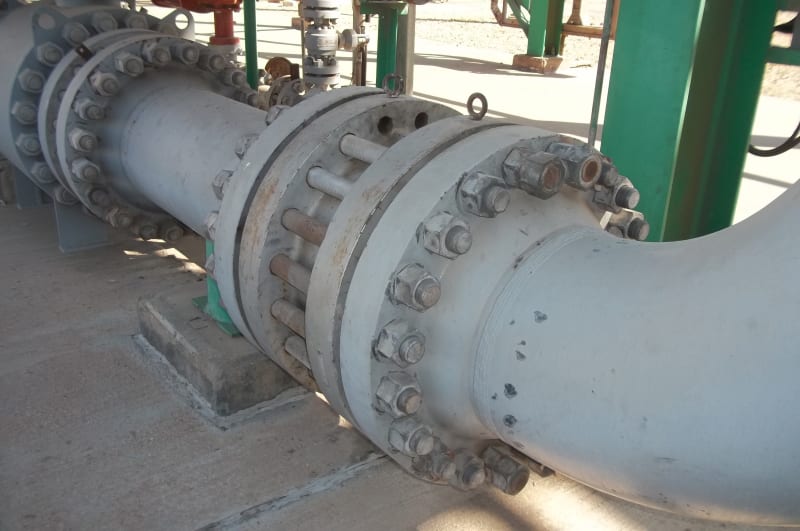
There's a wafer check valve # 900 which is installed with four semi-attached stud bolts (Locations # 1,2,15,16).

The valve is installed on a high pressure gas piping system with design pressure 110 bar & operating temp. 54 C

Even though the outer diameter of the four holes (53.5mm) is larger than the diameter of the bolt (51mm), the inner diameter of the four holes (47 mm) is smaller than the diameter of the bolt (51mm).

Also it is believed that these holes are threaded through half of the hole groove.

I need to know if there's a standard for the design of such flanges ( half groove threaded holes ) and to confirm that there is NO overload on the other stud bolts.

 
 https://files.engineering.com/getfile.aspx?folder=87fc7e41-1c51-476f-85b0-c4f91b25ba32&file=100_4333.JPG
Replies continue below

Recommended for you

download.aspx_yzxygu.jpg


--Einstein gave the same test to students every year. When asked why he would do something like that, "Because the answers had changed."
 
A,drawing would help but it looks like the top and bottom two studs are screwed into a tapped hole on the valve itself??

You need to look out measure how much those atuds are screwed into the valve. This needs to be at least the same depth as the nut on the other studs.

If this is the case then it's very odd but almost certainly still effective.

I'm not sure why those two studs are double bolted but it may be a way to screw the stud into the flange of the valve....

Remember - More details = better answers
Also: If you get a response it's polite to respond to it.
 
Replying to Gator:
The manufacture is CONTROLFLUID SRL
It's an old modeled valve & i've tried contacting them to get the related data sheet with no reply.
Replying to LittleInch:
A drawing isn't available.
My concern that overload may exist on the rest of the bolts as these bolts are 1,2,15,16 ( sequence of torque tightening ) so the torque isn't well distributed
I think if these bolts were 1,2,3,4 then it might have been better in load distribution over the rest of bolts
 
 https://files.engineering.com/getfile.aspx?folder=bf5fa783-56a4-479f-ac8c-127c0049a9f3&file=image001_(1).png
I can't see any issue here.

Is there an issue with this valve?

When you tighten no 1, 2, 15 and 16 just make sure you do both sides at the same time. Tightening uis a gradual process, so hand tight, then 25% of torque, then 50, then 85 then 100.

Or something like that.

You seem to be trying to find a legible which doesn't exist IMHO.

Remember - More details = better answers
Also: If you get a response it's polite to respond to it.
 
Looks like it was done to make installation and removal of valve easier since the lifting eye is centered between the threaded bolts, and may be easier for threaded bolts in this arrangement to be first to be installed during installation or last to be removed during removal of valve because valve can the be self supported from those 4 bolts even with all studbolts removed. it may even be the manufacturers standard design. Otherwise it was rigged in the field? But if they threaded 4 of same size holes of the studbolt holes in field then I believe then the diameters would then be larger not smaller, so it looks like it could be a manufacturer's design.
 
I've seen similar design at an oil refinery. I meant the a couple of holes bigger than the rest. It was awhile back and could not find it in any specific standards. In the end, it was the manufacturer design to facilitate installation for a big flange. Worst, it used JIS Standard for main flange dimension, which took me awhile to figure that out.
 
This valve was provided with tapped holes for the top and bottom two bolt positions on each side. There is a casting feature just visible at 12 o'clock (and presumably there is a similar one at 6 o'clock) that is preventing fitting a nut on the backface of the valve flanges in those positions, so tapped holes were required.

Curiously, wafer style bolting (one extra long set of studs) has been provided for the balance of the hardware for this double flanged style check valve instead of two sets of typical flange bolting.
 
It looks like a wafer style valve to me.

Not sure if the casting would allow any of the studs to be used with a large nut on them?

Remember - More details = better answers
Also: If you get a response it's polite to respond to it.
 
Only a double flange style body has a cast and machined full flange OD. It does look tight, but I think I can see nut marks on at least one bolt position.
 
Maybe. Only half the number of bolt tightening activities...

Remember - More details = better answers
Also: If you get a response it's polite to respond to it.
 
Status
Not open for further replies.
Back
Top