Continue to Site

Eng-Tips is the largest engineering community on the Internet

Intelligent Work Forums for Engineering Professionals

  • Congratulations KootK on being selected by the Eng-Tips community for having the most helpful posts in the forums last week. Way to Go!

Walking Column - Strut Capacity

Status
Not open for further replies.

EulersBucklers

Structural
Jun 25, 2019
5
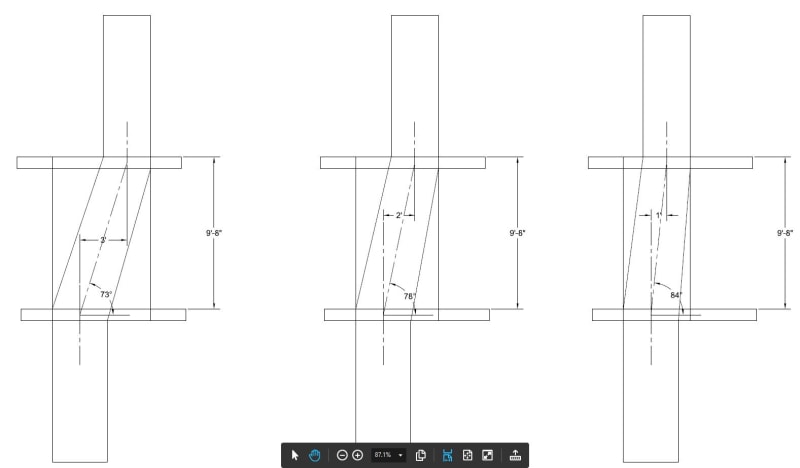
I have a column that the architect would like to walk over. Consider the top, transition and bottom columns to all be the same thickness into the page. I am in the United States so ACI 318 prevails.

I'm thinking of doing a strut and tie check in addition to some other checks and I am struggling with the strut capacity calculation. I am considering the strut in the transition column to be bottle-shaped and, per ACI, I would use a βs factor of 0.6 (without special transverse reinforcement) or 0.75 (with special transverse reinforcement). I want to reinforce the walked column conventionally with vertical steel and horizontal ties. Here is where I would like to see the forum's opinions:

1) Per ACI, I can't consider longitudinal reinforcement that isn't parallel with the strut axis in the strut capacity. This kills me if all my steel is vertical and horizontal and actually results in having less compressive capacity in the transition column as in the top column.
2) It appears to me like there should be an angle of strut inclination that should be "close enough" to parallel so that I don't have to disregard my vertical steel (maybe less than 10 degrees?). Otherwise you'd have to resort to inclined reinforcement which looks odd to me and seems unnecessary.

What does the forum think on this "close enough" idea? Maybe other codes have weighed in on this?
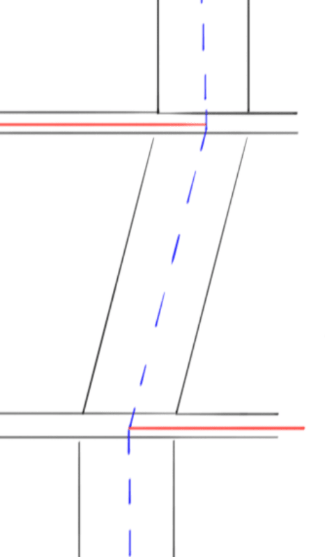
walking_column_hnf6lr.jpg
 
Replies continue below

Recommended for you

OP said:
Otherwise you'd have to resort to inclined reinforcement which looks odd to me and seems unnecessary.

I agree. I've certainly seen the inclined cage done but I prefer not to do that if possible.

OP said:
What does the forum think on this "close enough" idea? Maybe other codes have weighed in on this?

1) Practically, there must be some "close enough" inclination. That said, I've seen no formal recommendation on what that inclination might be.

2) I'd be very careful with the "close enough" strategy. Some things that worry me:

a) At the nodes on either end of the strut, you'll need to get the bar compression quickly, and convincingly, into the nodes. That may complicate detailing.

b) The bar compression in the verticals will need to walk laterally. This may not be a big deal but it's not something that's captured in our conventional STM's.

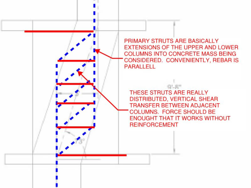
On occasion, I've used the strategy shown below. It is true that it is not the most direct load path and, perhaps, not the model most congruent with anticipated elastic stresses. That said, it does a much better job of jiving with conventional reinforcing schemes. In a way, it might actually be argued that this model does actually do a better job of capturing elastic stress distributions. After all, much compression will enter the system from the vertical steel in the columns above and below. That compression will dissipate into the body of the wallumn over a finite distance which is really just what the model reflects.

c01_tq83jn.jpg


HELP! I'd like your help with a thread that I was forced to move to the business issues section where it will surely be seen by next to nobody that matters to me:
 
Isn't this in part what the requirements in ACI318-14 in 23.5 are for? It gives rules for reinforcement requirements for the 'spreading' of bottle shaped struts that don't cross perpendicular/parallel to reinforcement? This in turn allows for a better βs factor. I'm sure earlier ACI versions also have the same criteria as my own local code (NZS3101:2006) is predominantly based on ACI318-02 from 15+ years ago and it has an almost identical criteria for this situation?

Capture_y9fvw9.png


Saying that I'd also probably review a similar model to kootk's and provide full column detailing confinement, I'd note the tie in the upper/lower slabs can also be a compression strut (or have some load going each way in tension and compression) to balance the load transfer. Really depends on what structure you have to resist the loads remote from the walking column I guess as to what mechanism is most appropriate.

Also consideration of the fact that these columns may take more lateral load by virtue of the increased stiffness should be undertaken. You could get in the situation whereby you chase your tail a bit, column needs to be larger for strength, attracts more load, needs to be larger/more heavily reinforced for higher loads, this makes it stiffer which means more load, rinse and repeat to infinity........
 
Actually, re-reading what you wrote, that doesn't answer the question I think. You are really talking about adding compression reinforcement to the longitudinal struts.

Basically for compression reinforcement to be allowed in a strut it has to be parallel to the strut, it does no good if it simply crosses the strut as you only have it in the strut for a brief period working along the strut. This contrains you I believe to kootk or similar derived model.

I would of course also check the requirement I referenced because even though you conceive this elaborate model in an effort to drive where the forces are supposed to go by providing capacity for that state of equilibrium, the forces try to follow your initial guess of the single bottle shaped diagonal strut.
 
Interesting questions.

1) I suggest tipping the cage. Wouldnt that better follow the load path? It sounds like some miserable detailing to do global verticals, no? Can you resolve the 2’ walk moment with your lateral shearwalls? Ultimately the axial load will be transferred between the column-slab joints. Reinforcing parallel to this line helps column/strut behavior.

2) regarding “close enough”— does P-delta for imperfections count as close enough? How far does that go? I think the “line” here is inherently hazy.

 
I also used to think that tipping the cage was the best solution from a mechanical perspective. As of yesterday, however, I've changed my mind and now believe that it's flawed in a way that makes it less desirable than the orthogonal layout both technically and from the perspective of constructability.

For the purpose of what follows, let's assume that we're talking about a column for which the reinforcing is required to help carry axial compression.

As I see it, there are two possibilities based on joint detailing and designer assumtions:

1) the verticals bend and lapped at the floor levels and bar compression is considered to be passed from cage to cage. I this scenario, the concrete will fail on the outside of the bar bends. Fail.

3) the vertical bars do or don't bend and lap at the floor levels but, either way, bar compression is not assumed to be transferred from cage to cage. In this scenario, the nodes most likely crush as a result of compression overload. Fail.

I anticipate that my stance on this will be controversial and I look forward to hearing what others think of it.


HELP! I'd like your help with a thread that I was forced to move to the business issues section where it will surely be seen by next to nobody that matters to me:
 
From an energy perspective wouldn't the single diagonal strut and tie at each floor be the least energy strut-tie model and isn't that the goal of the model?

Capture_rjdwrb.png


KootK said:
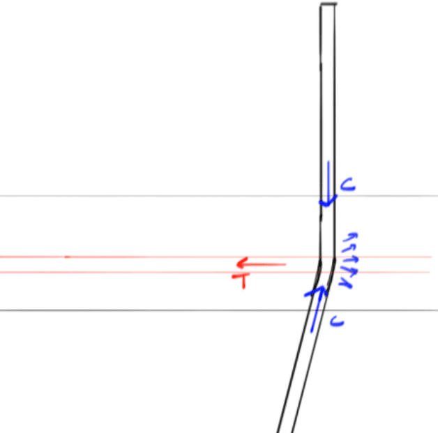
1) the verticals bend and lapped at the floor levels and bar compression is considered to be passed from cage to cage. I this scenario, the concrete will fail on the outside of the bar bends. Fail
Isn't that what the ties are there to prevent?
Capture_mcnuje.png


Open Source Structural Applications:
 
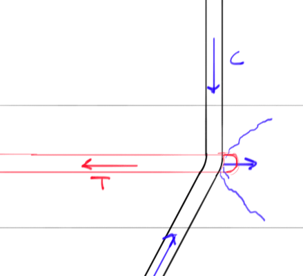
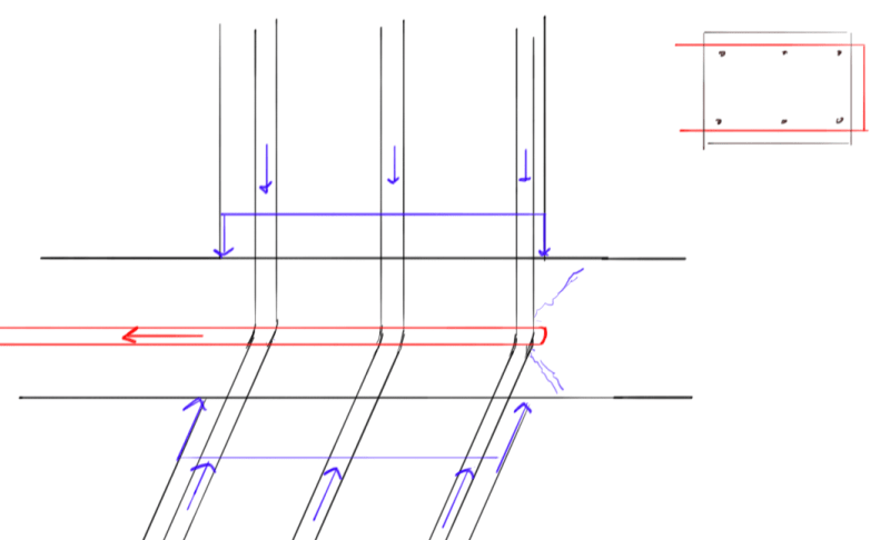
my last sketch had the exterior bar bend force acting like a curved bar node but thinking more I think it's more like a point force with a failure cone, so perhaps better detailing of the ties to engage this plane at each vertical bar set is needed. Which then leads to the point of more congestion in the slab...hmmm.

Capture_etfnbe.png


Open Source Structural Applications:
 
celt83 said:
From an energy perspective wouldn't the single diagonal strut and tie at each floor be the least energy strut-tie model and isn't that the goal of the model?

1) Energy minimization is one desirable goal but not the only one.

2) Constructability factors in heavily.

3) It's all for nothing if it falls apart at the details as, I believe, it does here.

celt83 said:
Isn't that what the ties are there to prevent?

I don't believe so. I don't see by what mechanism a conventionally detailed STM tie could prevent local concrete crushing on the outside of the bar bends. You might be able to deal with the stresses with hairpins etc but, given the size of the vertical bars, the radius of their bends, and the limited depth of the slab, I don't see this being a practical solution.

HELP! I'd like your help with a thread that I was forced to move to the business issues section where it will surely be seen by next to nobody that matters to me:
 
Celt83 said:
my last sketch had the exterior bar bend force acting like a curved bar node

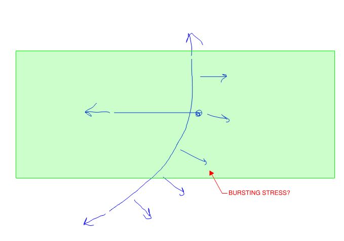
I can definitely get behind a reversed, curved bar node so long as there's a path for the stresses emanating outward from the bar bends. But I'm skeptical that's the case in most situations. And I'm even more skeptical that anyone's checking it which is, of course, another kettle of fish. A final wrinkle is that the vector sum of the curved bar node stresses won't actually be acting parallel to the slab. There will always be an oblique, bursting component.

HELP! I'd like your help with a thread that I was forced to move to the business issues section where it will surely be seen by next to nobody that matters to me:
 
KootK said:
A final wrinkle is that the vector sum of the curved bar node stresses won't actually be acting parallel to the slab. There will always be an oblique, bursting component.
Would the compression enveloped inside the column bearing area above/below the slab work to restrain/confine the bursting component?

Open Source Structural Applications:
 
Celt83 said:
Would the compression enveloped inside the column bearing area above/below the slab work to restrain/confine the bursting component?

For the verts on one side of the cages but not the other.

HELP! I'd like your help with a thread that I was forced to move to the business issues section where it will surely be seen by next to nobody that matters to me:
 
so would we then be talking about a hairpin tie that wraps at the end of the column only and not a hairpin per vertical set, I'd feel a little bit better about the detailing and congestion issues if this was the case.

Capture_fsqeks.png


Open Source Structural Applications:
 
That would be heading in the direction of a logical approach I think. That said, your sketches are showing sharp kinks in the column verts. For many serious column sizes, you'll be looking at outside diameters on the bends to the tune of 6" to 8" which starts to approach the depth of common slabs. As such, I start to question whether or not the curved bar node model can be resolved appropriately with a single, horizontal hair pin. Exaggerated condition below. We do something similar at 1:6 for column vert lap splices but, there, things usually balance out across the column with the opposing forces.

c01_vjtrum.jpg


HELP! I'd like your help with a thread that I was forced to move to the business issues section where it will surely be seen by next to nobody that matters to me:
 
KootK and Celt83 -

Thanks for the great discussion. I'm not sure that I can add much to the comments. But, I would like to suggest that the bars Celt83, along with the presence of the slab should provide some "confinement" of the vertical / bent bars. Enough to alleviate the concern about the bursting stress KootK is concerned about? Depends on the angle bend of the bars, the thickness of the slab and such.

I tend to prefer Celt83's suggestion, just because the load path is simpler / cleaner / clearer.
 
I appreciate everyone's thoughtful feedback on this. Thanks!

I agree that the kink in the rebar by the node appears to be the primary concern. As a matter of fact, I threw out the 10 degree limit because it matches the 1:6 of normal offset bars. If we put some real numbers to the situation I have with the 1'-0" offset I have approximately 250k of tie force and my verticals are all #11. My slab is 9" thick. I was planning on putting this thrust into my slab model and seeing how my design was affected (especially with the loss of precompression in the PT)...probably add a mat of steel top and bottom on top of my normal slab design. However, it seems like these U-bars should be hugging the verticals in which case I need some serious steel in a small area. Maybe 6 #6 hairpins top and bottom of the slab.
 
KootK said:
...That said, your sketches are showing sharp kinks in the column verts. ..
Yeah I got thinking about that and more or less sketched what you have in your post, makes that resultant bursting component stand out much more as not being the purely horizontal force I sketched, amazing the things you pickup on when you actual draw things to a correct scale.

I'd want to look into bringing column ties down into the slab to help along with the direct tie hairpin and maybe a localized column cap if I didn't already have a drop panel.

The single strut and top/bottom tie is the prevailing detail in my neck of the woods, although I doubt it has ever been given much thought beyond simple trig force resolution.

Open Source Structural Applications:
 
JoshPlum said:
Enough to alleviate the concern about the bursting stress KootK is concerned about?

I'm not yet convinced. I think that confinement is a whole different scale of issue from actually turning the force present in a gaggle of large diameter rebar 30 deg etc. At the least, if we're going to rely on confinement this way, I'd want to find a way to pus some numbers to it. Along the same lines, these "hairpins" may well need to be #8 bars etc in order to turn the forces present in large diameter column bars.

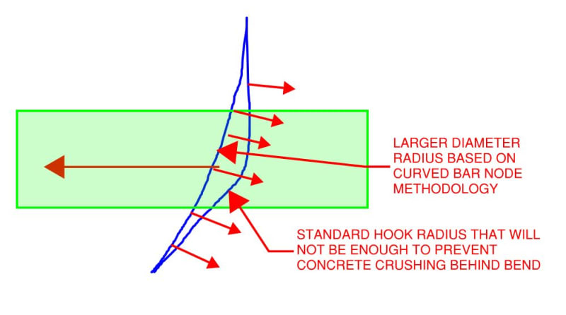
One thing that I forgot previously is that, to prevent concrete crushing behind the rebar, the bend diameters will need to be larger than the 90/180 hook diameters. I worry that things start to look as shown below where it becomes questionable whether or not a lone horizontal tie at slab mid depth is really doing a good job of restraining the curved bar bend. If there were more concrete mass around the joint, I think that a group of radial hairpins would be ideal.

Lastly, I worry about the impact of construction tolerances. When I've seen these joints in the wild, nothing about that experience has led me to believe that we'll have great control over the vertical location of the bend.

c01_dqgnao.jpg


HELP! I'd like your help with a thread that I was forced to move to the business issues section where it will surely be seen by next to nobody that matters to me:
 
celt83 said:
The single strut and top/bottom tie is the prevailing detail in my neck of the woods

#MeToo, I've done it myself. Last night, I discussed this with a friend who used to work for one of the highrise specialist firms in NY. Apparently their standard detail was the orthogonal reinforcing scheme and their primary check was shear friction on a vertical section through the wallumn. That check would be substantially in keeping with the STM that I proposed. I'm not necessarily saying that their way -- or mine -- is correct but it does serve as one, interesting data point.

HELP! I'd like your help with a thread that I was forced to move to the business issues section where it will surely be seen by next to nobody that matters to me:
 
KooK:
Interesting approach, I think if you have the wallumn then keeping things orthogonal probably makes sense for a lot of reasons. We usually end up being pressed to get a sloped column, so we hold pretty steady to a 1:6 slope limit and run that over a couple floors if need be, down in my region we're also not dealing with highrise so our forces are probably peanuts by comparison and things probably just work to the point that a lot of the mechanisms of force transfer get taken for granted.

Open Source Structural Applications:
 
Status
Not open for further replies.

Part and Inventory Search

Sponsor