Structure101
Structural
I am working on a tilt up concrete panel building and am trying to calculate the wall anchorage forces on a single concrete panel for embed plate with headed stud anchors design.
- I calculated the seismic anchorage forces based on ASCE Section 12.11.2.1 and I got Fp = 4.3 kips.
- However, at this location, wind governs and my diaphragm and concrete panels are designed based on in-pane and out of plane wind forces.
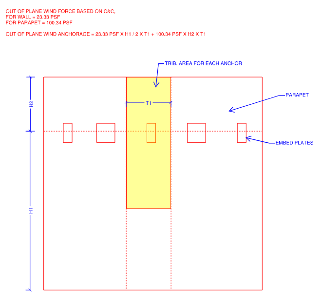
- I calculated the out of plane wind force for each embed plate and I got Fp = 7.6 kips. I have attached a image below.
Q1) Is the Seismic Anchorage Forces based on ASCE Section 12.11.2.1 out of plane or in-plane. If it is out of plane does that mean the diaphragm shear along that grid line is in-plane?
Q2) ASCE Section 12.11.2.1 states Fp is the design force in individual anchors. If I have 4 or 2 headed stud anchors in a single embed plate, does that mean I should multiply the Fp (7.6 kips) x No. of Headed Stud Anchors?
Q3) Am I calculating the out of plane wind force correctly?
- I calculated the seismic anchorage forces based on ASCE Section 12.11.2.1 and I got Fp = 4.3 kips.
- However, at this location, wind governs and my diaphragm and concrete panels are designed based on in-pane and out of plane wind forces.
- I calculated the out of plane wind force for each embed plate and I got Fp = 7.6 kips. I have attached a image below.
Q1) Is the Seismic Anchorage Forces based on ASCE Section 12.11.2.1 out of plane or in-plane. If it is out of plane does that mean the diaphragm shear along that grid line is in-plane?
Q2) ASCE Section 12.11.2.1 states Fp is the design force in individual anchors. If I have 4 or 2 headed stud anchors in a single embed plate, does that mean I should multiply the Fp (7.6 kips) x No. of Headed Stud Anchors?
Q3) Am I calculating the out of plane wind force correctly?