Eng-Tips is the largest engineering community on the Internet

Intelligent Work Forums for Engineering Professionals

WARPED CYLINDER HEAD QUESTION

Status
Not open for further replies.

MRSSPOCK

Mechanical
Aug 29, 2010
303
0
0
GB
I have never heard anyone discuss the implications of skimming a cylinder head, and often wondered why.
Suppose I have a twin cam cylinder head, and the camshaft axes are on the split plane where the rocker cover is fitted, and the rocker cover forms half of the cam journals.
Let's say when this cylinder head is manufactured, the distance from the fire-face to the camshaft journals is 100mm, thus the dimension from the fire-face to the rocker cover face is 100mm.
Now suppose a mechanic has removed my cylinder head to replace a leaking gasket, and he notices the cylinder head has a twist in it.
If he sets it on a surface plate, it rests on two diagonal corners, but a 1mm shim can be inserted into one of the other corners, to stop it rocking.
He takes the head to a machine shop.
The machinist sets the cylinder head down on his mill on the rocker face, and adds a 0.5mm shim at each of the relevant diagonal corners, so as to take away any rock, then the cylinder head is clamped to the milling machine table.
He then gradually removes material from the fire-face until he gets a clean cut, and in doing so, he has removed 0.5mm from the two high corners, and virtually nothing from the low corners.
He returns the cylinder head to the mechanic who rebuilds the engine, and that's the job done.

BUT hold on.
If the cylinder head had been measured with a micrometer after being removed from the mill, measuring from the fire-face up to the rocker cover face, the dimension would have been virtually 100mm in two places, but would vary everywhere else between 100mm and 99.5mm.
So when this cylinder head is clamped down onto the engine block, the rocker face will no longer be a flat face, but will have a 0.5mm deviation from flat, and as such, I would now have camshaft axes which likewise, are no longer straight.
This means when the cams are set into place, and the rocker cover clamped on, the camshafts are in reality being bent by a value close to 0.5mm over their length.
Does nobody think about this, or do they just not care about it?
 
Replies continue below

Recommended for you

I would think returning the rail for the rocker arm cover, and the camshaft bearing saddles to a planar surface would also be part of the repair process. Then, if line boring the camshaft journals cannot be done without without going to an oversize, the repair may become tricky indeed. But I think a standard size line bore would work, barring any extreme circumstances.
The other potential issue is, reduction of the centre-to-centre distance between the camshafts and the crankshaft(due to removal of material from the cylinder head deck), in principle, can affect the valve timing. Not having made any effort myself to quantify the effect, for all I know, it is inconsequential.

"Schiefgehen wird, was schiefgehen kann" - das Murphygesetz
 

I'm not sure what effect 450 to 500 degrees Fahrenheit for four hours has on typical aluminum heads.
If it also relieved the stresses securing the valve guides and seats I would not consider it a proper procedure.

As long as the cam turned freely in the valveless unclamped warped head or machined bent head (free or installed, assuming similar flat gasket surface condition) I'd be tempted to leave it alone.
 
Couple of points in response..

1mm (about .040") is a substantial amount of head warpage. it's possible to correct more than that- I've seen heads warped .085" (about 2mm) corrected on pushrod engines where there is no cam bore in the head, but it's not a simple process and attempting to correct that much warpage carries risk that the head will become a paperweight after.

So, point is, typical repairs for warped heads are dealing with a corner-to-corner warp of .010"-.025". It takes a LOT to warp a head more than that.

The typical process if there is significant warp in the deck surface is to straighten the cam bores first, not second. On most SOHC or DOHC cam heads, there is enough material connecting the cam bores to the deck that if the cam bores are straight, the deck will be very close. On warped Honda B and K series heads for example, if the cam bores are within .003" (which is the upper limit) then the deck will usually be no worse than .008"-.010", which means you only have to cut the deck by that .008-.010. In the grand scheme, lowering the deck by that amount is relatively minor.

As far as this concern:

Lou Scannon said:
The other potential issue is, reduction of the centre-to-centre distance between the camshafts and the crankshaft(due to removal of material from the cylinder head deck)

There is no change in camshaft C2C distance by straightening the head, or line boring the cam journals .002"-.003". There is a change in camshaft to crank C2C when you cut the deck obviously, but it's so small that it can be absorbed easily when the engine is re-assembled and cam timing is set. .008" off of a typical deck interface will affect cam timing by about 1 degree, which is minor unless you're dealing with some super precise racing engine setup. If it's an issue, thicker head gaskets solve the problem pretty easily.
 
Thanks for all your replies.
I'm glad every one here is thinking in a similar way to me, i.e. that it is important.
However, I listen to many mechanics who routinely send heads to be skimmed, but I know for certain that is all that is being done.
Cam bores are not being re line-bored.
The heads are generally back in an hour or two, and all they ever send off to be machined is the head.
I generally just bite my tongue and say nothing, and leave them to it.
I often wonder when a cam snaps near its midpoint for no apparent reason, could it possibly be a casualty from such an operation, where the cam is being bent into shape, then the perpetual bending action at the midpoint, as it rotates, causes a fatigue failure.
 
Are they decking heads in order to restore surface finish for a new gasket intstallation (in which case they should be flycutting a couple of thou and not more) or to fix a warped head?

If a head is warped a couple of thousandths, it is possible to just deck the head and be done. How far the head can be warped without straightening prior to machining the deck is going to be different for each engine.

They also may very well be straightening the head first - the process doesn't take very long.

As far as breaking camshafts - this is a common symptom of an engine running too hot. The center of the head sees more heat than the ends to, and the cam bearing blocks/buttresses in the center 'grow' more than the ends. This can put a lot of strain on a cam between the center pair of cam bearings, whether the head itself is properly flat or not.
 
Good discussion above but the bottom line in these discussions for me is always - Does the part meet print or not? Every head has a manufacturing tolerance. Used parts could need one op or 500 ops to bring them back within tolerance, only careful inspection can determine what is appropriate for any given part. If the cam bores are straight and located properly after decking then there may be no need to bore. Easy as it is to simplify and say that a head is one structure that bends uniformly throughout, nothing could be further from the truth - BTDT FEA many times.
 
There is no change in camshaft C2C distance by straightening the head, or line boring the cam journals .002"-.003". There is a change in camshaft to crank C2C when you cut the deck obviously, but it's so small that it can be absorbed easily when the engine is re-assembled and cam timing is set. .008" off of a typical deck interface will affect cam timing by about 1 degree, which is minor unless you're dealing with some super precise racing engine setup. If it's an issue, thicker head gaskets solve the problem pretty easily.
Which is why I added the sentence after the one you quoted:
Lou Scannon said:
Not having made any effort myself to quantify the effect, for all I know, it is inconsequential.
[wink]

"Schiefgehen wird, was schiefgehen kann" - das Murphygesetz
 
GregLocock said:
I've only ever had heads skimmed. So are you suggesting bending the head straight? I see the logic, just haven't seen the gear in engine shops to do it.

Link
These guys have the gear to straighten a crankshaft - no doubt they could do a cylinder head.

Jump to 33:00 to see the crankshaft straightening. I had to watch the entire video to watch all the stunning creativitiy and skill. (No crankshaft grinder, no linisher, no mig welder, no welding helmet (put the sheild on your knees, one hand holding the welding stick - one hand rotating the crank)


je suis charlie
 

A crank breaking anywhere but in the journal fillets is interesting. What appears to be a flame cut surfaces is also curious.
I'll try to watch the video at home to see what's up.

Certainly in the link the alignment of journal's halves and the relative clocking of the front and rear throws is checked diligently and adjusted many times.

I did not see any clocking checks made after welding, but the presswork required to straighten the welded crank rlative to the adjacent journals is what I'd expect from any welded component.
Similarly the straightness after removing so much weld metal should not be ignored.
 
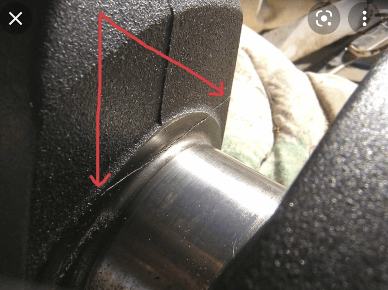
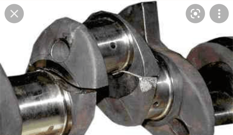
A quick Google of broken crankshaft pictures shows the break typically starts at the journal radius and proceeds through the web.

Some examples stolen from the web:

Screenshot_20220111-102242_rmktkv.png

Screenshot_20220111-102355_ekhvme.png
 
A mistake...... I missed it and can't be edited now.

I meant to say OHC Over head cam.


(
enginesrus (Mechanical)
10 Jan 22 06:51
And is why the OHV head would need to be straightened before surfacing it.
)
 
Status
Not open for further replies.
Back
Top