Continue to Site

Eng-Tips is the largest engineering community on the Internet

Intelligent Work Forums for Engineering Professionals

  • Congratulations KootK on being selected by the Eng-Tips community for having the most helpful posts in the forums last week. Way to Go!

Warping due to heat-affected zone 1

Status
Not open for further replies.

Lsos

Mechanical
May 15, 2011
11
Gland_brlsii.png


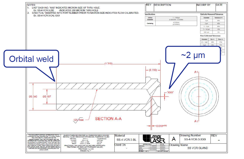
I am looking into orbital-welding the shown stainless-steel part to an ss tube and some couplings. However, some colleagues have expressed concerns that the welding process will warp the tiny, tiny 2 micrometer restriction hole at the end, possibly closing it or making it too large. I have a hard time believing that it will warp significantly (the tolerance on the hole diameter is already 20%), but I how do I convince them of this (if I am right)?

It seems that bending or stretching of the part should have minimal effect. Diametrical shrinkage or swelling would, at worst, have the same effect on the hole as on the whole part, so unless it's in the 10s percents, it won't be noticeable. Not to mention that the heat has a long way and a lot of material to go from the welding site to the restriction hole. We could also reduce the diameter of the tube at the welding site (it's outer diameter is too large anyway). Is there anything missing or incorrect from my logic?
 
Replies continue below

Recommended for you

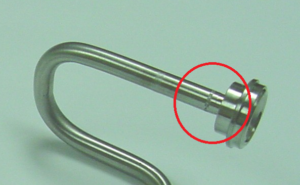
Orbital-welded, which is basically a fully automated gas tungsten arc welding process (GTAW).

Here's an example of what such a weld would look like on similar parts:

1_motlqh.png
 
Sorry, I completely missed that detail.

I agree that it's a nonissue from experience with other microwelding applications, but I would struggle to provide objective references.
 
In the world of designing welded structures for automated machines the common practice is to do all precision machining AFTER welding, but I don't know if that would really apply here.
 
The way to achieve even a 20% tolerance on such a small hole, is to make lots and throw away the (most) which don't comply. So indeed, we though about doing the machining after the welding, but then the cost would skyrocket by an order of magnitude. These are ultra-clean (thus ultra-expensive) parts.
 
Not sure, but is the hole measurable after welding on a short tube stub? If so, I'd weld on a short stub to several samples, and measure the hole before/after to verify any distortion. For a "micron sized hole" I'm not sure how many measurements you'd have to make to verify that any apparent differences between the before/after measurements are noise and not a real effect of the welding.
 
Even if the hole is difficult to measure the operating characteristics should be verifiable. Even if the only reason was to produce something extruded to that diameter, one can measure the product.
 
Have you looked into adding a temporary heat sink to the part being welded?
B.E.

You are judged not by what you know, but by what you can do.
 
If the difference was in the realm of noise, I would just take that as a non-issue, since anyway the tolerance on the diameter is ~20%.

Still, we are nonetheless interested in the end product, which is a very small flow of gas through the hole. We can measure it, and we can do it before and after welding. But, by the time we get this thing shipped from the other side of the world, then get it tested, then get it welded, then get it tested again, then do it all again with a heat sink, +/- bureaucracy and red tape, it will be a loong time. In the meantime, we have a half-assed "plan-b" which we know will work, but it's ugly. And I would like to avoid it, hence the question.
 
I like Berkshire's ides, make a copper heat sink clamp to put around the part.
I'll wager that if the welding is done correctly you cold hold the end with a bare hand.

= = = = = = = = = = = = = = = = = = = =
P.E. Metallurgy, Plymouth Tube
 
It should not be an issue if the delta T is less than 200 degrees F. Thermal gradients below that temperature will produce stresses in the elastic range, thus are recoverable. As the part with the hole in it is some distance away, the thermal gradient should not be that bad. The temperature should be fairly uniform by the time it gets to that portion of the assembly. The alternative is to use a heat sink. What is the material of construction? If it is austenitic stainless. the heat sink is not a bad idea. You could wrap copper tubing tightly around the pipe and pump water through it. I've don't it with type 316 stainless and it work very well.

Best regards - Al
 
"...I like Berkshire's ides, make a copper heat sink clamp to put around the part..." and inside the part and not excessively long so as not to cool the weld too fast.
 
Assuming this is an austenitic stainless, rapid cooling isn't an issue.

Best regards - Al
 
The diameter of the flow orifice is incredibly small (0.000079") and the orifice length tolerance is quite tight (0.010" +/-0.002"). The wall of the tube at the butt weld location (0.076") is fairly thick and the OD (0.340") is small in comparison. But there is a fairly large axial distance between the orifice and butt weld location (>1.0").

With such a small diameter flow orifice, the biggest concern would seem to be slag from weld drop around the tube ID breaking loose and clogging the flow orifice.
 
There is no slag and minimum spatter with a properly qualified GTAW process.
 
Thank you all for the suggestions and feedback. I can't be sure I will utilize it in this instance, but it definitely is good knowledge for the future. More is always welcome, of course. Due to the holiday season we are stuck regarding what to do for now.
 
there will have to be a weld fixture to perfectly align the two parts. then tack it in place. the part is so small there will be excessive heat affected zone. this is a challenge. there will be damage cause by the heat affected zone. the welding will have to be executed perfectly. placing a heat sink would help, but this part is so small it will be difficult at best. I think your colleges have a valid point. and there will be heat shrink from the parent material being consumed. which will shorten the length. but it is so small it may be negligible. the best option is to do test before and after , and adjust as necessary. Inspecting a 8 millions diameter hole ? how is that done by the fabricator. even manufacturing it will be difficult no less inspecting it. is there other parts fabricated this way and inspected? if so get with them and Investigate how it is inspected.
 
I think 2 um is about 80 "millionths" of an inch, or approaching 0.0001" or 1 "tenth' ( ten thousandth ).

Still a mighty small hole.
 
Hi Tmoose

My notes
1 um =1 micrometer = .000039370078
2 um = .00007874

is this not correct ? this what Terry also calc.

 
Status
Not open for further replies.

Part and Inventory Search

Sponsor