Eng-Tips is the largest engineering community on the Internet

Intelligent Work Forums for Engineering Professionals

Water flow rate at temporary hydrant 1

Status
Not open for further replies.

linemesomepipe

Civil/Environmental
Apr 3, 2024
3
0
1
CA
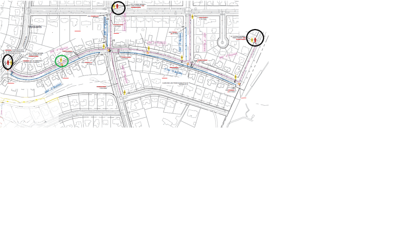
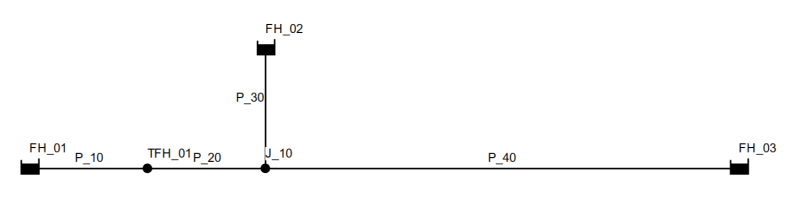
Rookie at this group and hydraulics isn't my forte. Got presented with a problem. Setting up a temporary bypass above ground system for potable water. Our feed hydrant is 4inch, connected via a 2inch backflow preventer into a 4inch temporary bypass (PVC). The feed hydrant static pressure is 80PSI. No bypass has been laid at and we had a meeting with the fire dept last week and they stated a requirement of 500GPM. I'd say the total bypass length is 1000ft and is feed by 3 hydrant feed- all at 80psi within the perimeter of the project. If I were to gauge the flow rate at a temporary hydrant of 4inch size that is connected to the temporary bypass, what pressure can I expect? Please let me know if any further info required but these are all that's give to me. Thank you
 
Replies continue below

Recommended for you

Need the configuration. Where are the water supply source connections and your offtake outlet??

500 gpm through the entire 1000 ft of 4" pvc gets a 50 psi pressure loss.

If you have two 500 gpm source points, one at each end of 1000 ft pipe, it could be around 12psi pressure drop to the midpoint.

--Einstein gave the same test to students every year. When asked why he would do something like that, "Because the answers had changed."
 
So the configuration is as the schematic below. Circled in black are the feed hydrant operating at 80PSI. This will be in service feeding the yellow temporary hydrants. My dilemma is figuring out what the GPM is for the hydrant in yellow. Assuming no homes is connected to the temporary system during testing.
Feed_asqy11.png
 
I set up a quick model in EPANET, assuming a flat site (I used elevation 0.00 as the datum) and the following pipes:
- West hydrant to temporary hydrant: L=550 ft, d=4", Hazen-Williams C=140
- Temporary hydrant, east to intersection: L=500 ft, d=4", C=140
- Intersection to north hydrant: L=500 ft, d=4", C=140
- Intersection to east hydrant: L=2000 ft, d=4", C=140
(the lengths are guesstimates and I used nominal diameters instead of actual diameters because it was faster to do so)

I set constant head reservoirs at the west hydrant, north hydrant, and east hydrant, each at 80 psi (184.5 ft head), and I set a 500 gpm demand at the temporary hydrant.

My model gives a pressure of 70 psi at the temporary hydrant. The west hydrant contributes 270 gpm, the north hydrant contributes 156 gpm, and the east hydrant contributes 74 gpm.

Rather than give you my file, I suggest you download EPANET (it's freeware from the US Environmental Protection Agency), learn the software, and set up your own model using real data. I am skeptical that all three existing hydrants will actually operate at 80 psi, but maybe it's true.

As a hint, here is what my simple model looks like.
Temporary_hydrant_1_ba70rz.png


============
"Is it the only lesson of history that mankind is unteachable?"
--Winston S. Churchill
 
OK. You are with fel3 now.

--Einstein gave the same test to students every year. When asked why he would do something like that, "Because the answers had changed."
 
Status
Not open for further replies.
Back
Top