Continue to Site

Eng-Tips is the largest engineering community on the Internet

Intelligent Work Forums for Engineering Professionals

  • Congratulations IDS on being selected by the Eng-Tips community for having the most helpful posts in the forums last week. Way to Go!

water leakage rate

Status
Not open for further replies.

wes123

Mechanical
Apr 22, 2018
4
Hi guys/gals

I am trying to find out the water leakage rate from a closed loop system through pressure drop.

or if someone knows the formula for how much water input is required to increase pressure that would also work.

the system volume is 1200Litres
Pressure drop is 5bar to 4 bar in 90 minutes

it must be possible but i cant find anything online so far.

thanks
 
Replies continue below

Recommended for you

There is an equation in BS-PD 8010 section 11.6.5 which lists the theoretical pressure volume slope, reproduced below.

All SI units
D (m) - OD
V (m3)
t (m)


The theoretical slope should be calculated using equation (19).
ΔV/ΔP= V(0.044D/t + 4.50) 10−4


See if that works.

It will be a small volume.

Also look up the FAQ on temperature change in this forum

Remember - More details = better answers
Also: If you get a response it's polite to respond to it.
 
You have not present much information. Do you have a diagram or picture? A picture is worth a thousand words.

What is the pipe diameter?

With only 1200 liters capacity, why can't you observe the water leakage?

 
Thanks for the replies,.

The system is a geothermal heat pump circulation loop buried approximately 1m below the surface. Hence why it can't be observed

The pipework consists of 1200m of 32mm plastic pipe and 150m 65mm plastic pipe. The temperature over the test time is constant at approx 10 degrees c.

We are unsure if it is the 65mm or the 32mm. But as most fittings are 65mm tee joints with 32mm reducing legs we are presuming 65mm.
All the 32mm pipe are continuous runs without joints

The fittings are electro fusion weld

The diaphragm expansion vessel has been removed for the purpose of this test. And all air released through auto air vents and purging. (now closed for this test) so we assume 100% of the system is water.

@littleinch thankss for the formula I am Assuming D is diameter and overall diameter so I will have a play with it and see what I find.

Thanks
 
wes123 said:
...all air released through auto air vents and purging. (now closed for this test) so we assume 100% of the system is water.

wes123 - I don't think the system is leaking. Will explain my thoughts below. However, there is any easy test:

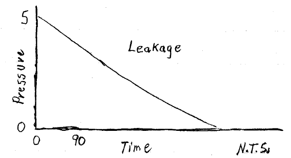
Start the test exactly the same way, but continue monitoring pressure for a lot longer than 90 minutes... say at least 900 minutes. If 100% of the air has been removed and there is leakage, it should continue past 90 minutes with results that look something like this:

Leakage-1_lvrz7y.png


Even if some air remains, say that 99.9% of air was removed, per Boyle's Law I get a volume change of air of of 0.24 liters for a pressure drop from 5 bar to 4 bar. That is not much of a change. The system has a huge ratio of plastic pipe surface area to system volume. Plastic pipe expands (a little) under pressure.. and it would not take much expansion to account for the small volume change. I wager that the test is performed with the system at ambient pressure, then (fairly quickly) pressurized to 5 bar.

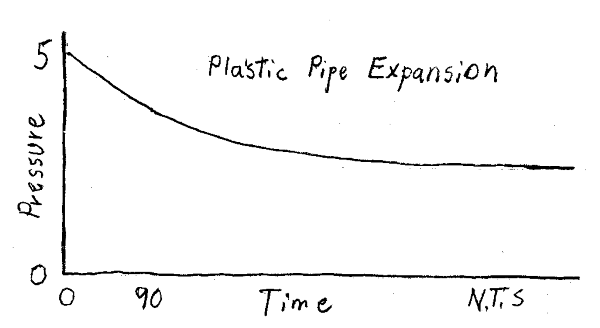
The plastic pipe then slowly expands under pressure, causing the pressure drop. Conduct the test as I described above (monitor pressure for a long time). If pipe expansion is the cause of the pressure drop (and there is no leakage), results should look something like this:

Expansion-1_onbawx.png


[idea]
[r2d2]
 
That equation is only valid for steel pipes.

PE pipes creep under pressure so testing is undertaken on a decay curve just like SRE has drawn.

Search for pressure test PE pipes if indeed "plastic" is PE.

Remember - More details = better answers
Also: If you get a response it's polite to respond to it.
 
A longer test will eliminate the pressure change from the water cooling off after fill as well. (It could heat up, offsetting some pressure loss, but that's not likely that shallow. 1200 meters is a long exposed surface of plastic pipe.)
 
Be sure to purge the air. It is difficult to purge the air in the pipe because of the long length of the pipe.

Purging

Another thing about geothermal pipes is that the polyethylene may stretch under certain temperature conditions. This leads to misinterpretation of the pressure readings. If pressure testing over a short period of time, you may see the pressure drop and assume you have a leak in the pipe, when in actual fact, the pipe is stretching. For this reason, it’s important to conduct pressure testing over a longer time period. Be sure to pretension the loop with hydraulic pressure before taking final pressure measurements.


Loop Leak Verification
 
thanks everyone for the replies.

the information about the expansion of the pipework is really good.

So after carrying out further tests it does look that the expansion from 5-4 bar is present but also coupled with a leak.
The water pressure does continue to drop but at a much slower rate.
this would be due to the lower pressure pushing the water out of the hole.
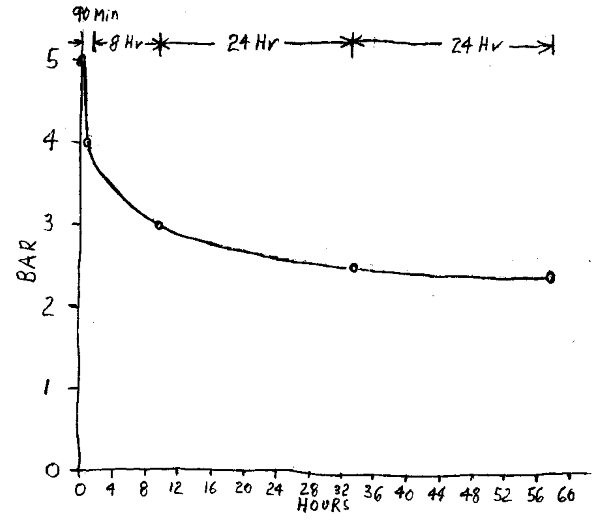
The pressure continues to drop from 4-3 bar in 8 hours and from 3-2.5 in 24 hours.
then only drops .1 bar the next 24 hours.

i think to offset 3 bar of pressure is quiet difficult on expansion of the pipe but could i be wrong?

i will continue to monitor over the next week and see what happens.

would it be more beneficial to leave the filling loop on continuously at 5 bar for a day or so. then carry out the test after as this would offset the expansion of the pipe right?

thanks
 
what is the design pressure / SDR / strength of the pipe?

Look at this guideline from a vendor
Pages 74 & 75 refer to testing and the logarithmic pressure decay curve calculation.

There are bound to be other such documents available on the web if you look properly.

The Plastics Pipe Institute is a good source and the relevant section on testing is attached.

If you have the filling loop on at 5 bar then somewhere at your weakest point your system is just gradually getting bigger and bigger until.....

Remember - More details = better answers
Also: If you get a response it's polite to respond to it.
 
wes123 said:
So after carrying out further tests it does look that the expansion from 5-4 bar is present but also coupled with a leak.
The water pressure does continue to drop but at a much slower rate.
this would be due to the lower pressure pushing the water out of the hole.

wes123 - You are looking at the "change in the numbers", and that is important. Sometimes it is better to look at the "rate of change in the numbers", this is much easier to do, by eye, with a scaled graph... often drawn by hand, with a pencil on graft paper... no computer or software required (although you could do it that way if you want to).

In 10 minutes time, I plotted your results (as I understand them).
Note: In this scanned image you will not see the lines on the graft paper, but they are there:

Pipe_Pressure_Loss_-_Rev_1-1_zgsdhz.png


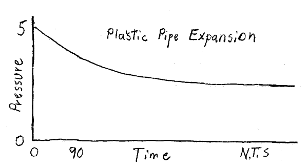
To me, this looks very much like the conceptual "no leakage concept" plot that I sketched a couple of days ago:

Expansion-1_qasde6.png


Does your test "prove" that the system is NOT leaking... NO.
Should you test for a longer time? The test is easy, I would. Edit: But at no higher than the design pressure, per comments by Little Inch.
But at some point, you will have to decide if test results indicate leakage or not... and what to do next.

[idea]
[r2d2]
 
Status
Not open for further replies.

Part and Inventory Search

Sponsor