Eng-Tips is the largest engineering community on the Internet

Intelligent Work Forums for Engineering Professionals

  • Congratulations waross on being selected by the Tek-Tips community for having the most helpful posts in the forums last week. Way to Go!

Water Splash Height - Calculation

Status
Not open for further replies.

EliteConsulting

Civil/Environmental
Nov 29, 2021
3
0
0
US
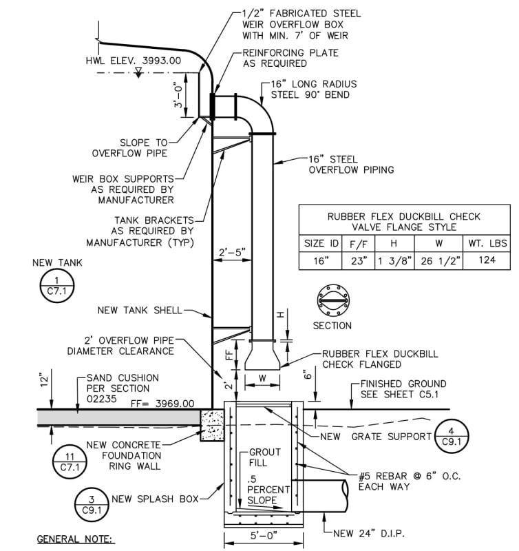
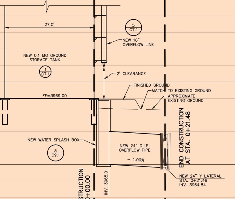
What are the most realistic workflows/methods to theoretically estimate the maximum height of water that will splash out of the concrete box after it has been discharged from the 16" overflow pipe draining the vented water storage tank?
Preferably utilizing:
a) Weir formulas
b) Bernoulli's equation
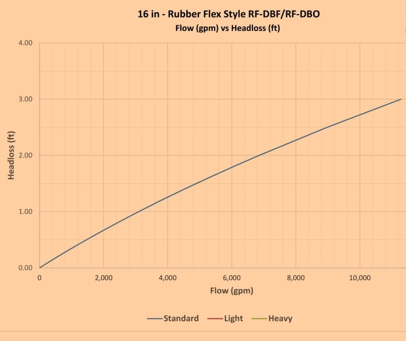
c) Accounting for head losses (please refer to attached graph)
16_in_-_Duckbill_Valve_Head_Loss_Graph_km4n65.jpg
Splash_Cacls_Diagram_ntxzaa.jpg
Splash_Cacls_PP_lmggp7.jpg
 
Replies continue below

Recommended for you

Velocity of falling object, including water
V^2 = 2gH
H = 10 m
g = 10 m/s^2 (actually 9,81, but the math is easier using 10)
V^2 = 2 * 10 * 10 = 200m^2/s^2
V = 200^0.5
V = 14.14 m/s

Bernoilli head, or height = H = v^2 / 2g
H = (14.14m/s)^2 / 2 / 10m/s^2
H = 200/ 2/ 10 = 10m

Theoretically it could be the same as H, but rebound is not perfect so estimate 50% of H
Anything bouncing straight up off the grating would be beat back down by the falling water above, which should limit trajectories to those outside the diameter of the falling water column.

Just did the experiment. Free falling water from a tank gave a maximum drop splashback of 50% H. 1.25m tank outlet height had a highest drop splash of 60cm. The splash pattern looked like a normal distribution curve; effect of other trajectories involved.

Your pipe mouth looks like it would interfere with splash back, so maybe you could limit the trajectories to lower angles???
 
The flow regime in the down pipe will result in much lower velocities as the level rises.

Initially will be annular flow, then a few drops in the middle, but velocities are not as simple as calculated.

why do you want or need 2' clearance above the pit?


Remember - More details = better answers
Also: If you get a response it's polite to respond to it.
 
Very interesting topic. I have never evaluated or come across this in my career. Just a thought, the use of a wet sump below the invert of the outlet pipe should damp out the rebound.
 
LittleInch...

USEPA requires an air gap: This document says 3x the pipe diameter above the storm drain, but doesn't specify if this means above the storm drain grate or above the storm drain pipe in the box. I think it's above the grate* and I'm sure the exact requirement is buried deep in some code that I don't have time to look up now. If it's 3x the pipe diameter above the grate, then the 24" shown in this detail isn't adequate.

* It's been about five years since I last dealt with this requirement and my memory isn't what it once was. On the other hand, I have a vague memory that years ago the requirement was 2x the pipe diameter.

EliteConsulting...

Totally unrelated comment: your detail implies that the finished grade matches the top of the ringwall. I suggest instead that you grade the site such that the finished grade is below the top of the ringwall a sufficient distance to prevent water ponding at this location. I have looked at quite a few tanks where the finished grade matched the top of the ringwall and all of them showed considerable corrosion on the outside of the floor plates. A poor paving job or even slight settlement can make the ringwall a low point and water can pond here. On the other hand, I have never seen significant corrosion here when an adequate curb height has been provided. I always use a minimum curb height of 6".

============
"Is it the only lesson of history that mankind is unteachable?"
--Winston S. Churchill
 
@1503-44:
Thank You for your input.
By the way, what a coincidence!
A colleague ran a similar experiment and concluded a maximum drop splash back of 35% H.

@LittleInch:
I appreciate your input.
A clearance above the pit is required by EPA as previously mentioned by fel3.

@fel3:
Absolutely.
An actual grading plan has been provided on its respective plan sheet.
Good catch!
 
Yeah, lots of the drops hit around 30-40%, but 50 was the absolute highest. I feel that after time passes it could make a significant mark.

 
Why do you want to know? Doesn't it rain there?

Just curiosity?

Remember - More details = better answers
Also: If you get a response it's polite to respond to it.
 
We do actually have some water tanks around. In fact when climates are usually dry, you may find more water tanks than in areas where it rains a lot. We can't just tap any ole lake or river that happens to be nearby. We've got to catch it, sometimes directly from the clouds, and save it for later. Some of the extinct volcano cones are used in place of tanks too. There is one about 300m high about 1.5km away that supplies our water. Plenty of pressure. I should check to see of we can run a turbine with that and make some electricity on the side.

 
@LittleInch
it was inquired by project's owner.

@cvg
Thank You!

@Compositepro
Good point!
What's the highest elevation that water will accumulate, if any, in the basin?
 
I could understand the requirement for 2x diameter separation for the overflow pipe if there was a possibility of a back siphonage condition to exist, but there isn't that possibility. If the tank suddenly begins to drain, there will no longer be any hydraulic connection between the overflow pipe and the water in the tank.
 
We did a box like this for a backwash sump on a filter. The box was 6' deep. We cut a hole in the grating where the water fell through unimpeded by the grating. There was no splash back into the building. The box was sized empirically from another pre-existing design. A 6' deep box would allow 4' of cover over your 2' drain pipe. The cover over your drain pipe may set the minimum depth of the box.

Tanks like this would typically have a high level alarm set at 90% full. Your HWL is set too high as it is above the straight side height of the tank. The HWL is also shown incorrectly as it would have to be at least several inches above the 3' high weir. The several inches are due to the water flowing over the weir at the maximum rate.

How do you propose to apply a coating on the steel weir box? It is not constructible as shown.

What is the overflow flow rate? Does the 24" drain pipe have the capacity to drain the overflow?

Why do you have the weir structure in the tank? Most overflows don't have interior weirs. Once the water level rises above the overflow pipe, the pipe will flow full.

Most overflows from tanks use just a splash block and overland flow to drainage. Do you expect to have periodic overflows?
 
Status
Not open for further replies.
Back
Top