Continue to Site

Eng-Tips is the largest engineering community on the Internet

Intelligent Work Forums for Engineering Professionals

  • Congratulations pierreick on being selected by the Eng-Tips community for having the most helpful posts in the forums last week. Way to Go!

Web penetrations in steel channel sections 1

Status
Not open for further replies.

Agent666

Structural
Jul 2, 2008
3,080
All of the current advice I'm aware of with respect to web penetrations in steel members (AISC design guide 2, AS/NZS2327 and SCI p355) only covers the treatment of web penetrations in i-section members.

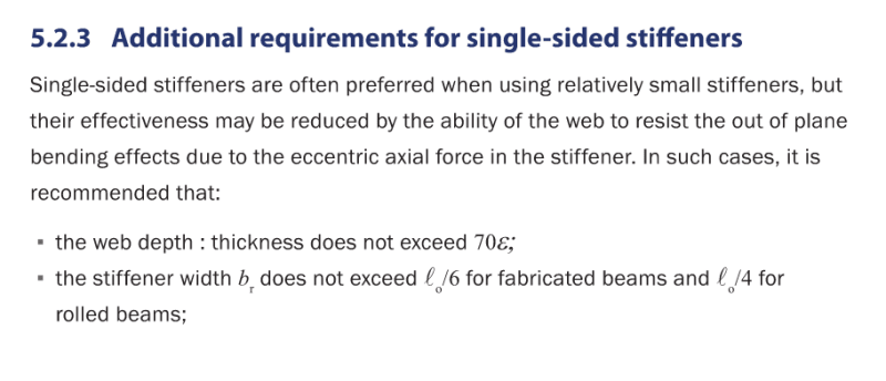
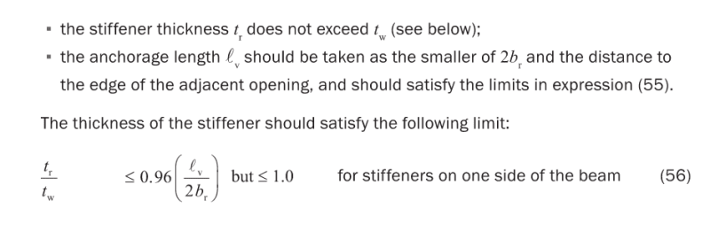
P355 sort of mentions some of the concerns I have with a non symmetrical tee (web and single sided flange) when it discusses single sided stiffeners. But otherwise no commentary or design methods for anything but doubly symmetric sections. Maybe I'm overthinking it though...

Wondering if anyone's come across any recommendations for penetrations in singly symmetric sections like channels.

My current thoughts were to add another stiffener opposite to the channel flange, effectively widening the flange to be more or less symmetrical. Then just apply the normal rules for a symmetrical tee locally to the penetration?

Mainly talking circular penetrations at this stage if it matters...

Thanks.

 
Replies continue below

Recommended for you

Depending on the size of the penetration I'd be using a pipe segment welded around the penetration in the web. For a rectangular hole I'd use horizontal reinforcing plates above and below the penetration that run parallel to the beam. The same as I would do for an I section.
 
Can you elaborate on your concerns? The obvious complication is the twisting of the unsymmetrical tee that adds stress to the flange.
 
Yeah thats it exactly, you're effectively trying to bend a top/bottom 'tee' (which is really similar to an angle), about a non-principle axes. Not to mention the whole compression/tension centroid being offset from the web.

This is what P355 had to say on the matter of single sided stiffeners located at the top/bottom of the hole, and the concerns around the non-symmetry of this scenario. But these recommendations are on the assumption your flange is symmetrical.
Screenshot_2022-03-10_153025_pv9c8g.png

Screenshot_2022-03-10_153051_svab2h.png


Can you give me a hint about what epsilon is, and what expresson 55 is? Thanks...

Rather than think climate change and the corona virus as science, think of it as the wrath of God. Feel any better?

-Dik
 
Dik you can download the full guide here.

Epsilon is a scaling factor for yield strength.

See page 65 for the eqns 55, it's basically a number of checks to determine the minimum anchorage length for any stiffeners beyond the edge of the opening.


Can you provide the reason for the use of Channel section and the size of hole if small or not?
SCI P355 is for design of composite beams with large web openings..

I agree with the concern and SCI P355 , AISC Steel Design Guide 2 and ASCE 23-97 silent for the channel sections ..

If the use of channel section is a must IMO , you have two options;

- Either Shift the hole location to around the midspan where shear is minimum or zero if possible ..( i do not have any idea for the seismic loading )

- Or Add stiffeners to the flange so literally the section will be I-section..

Shear is bad boy if the section is not symmetrical for both axis..
 
Anything over 10% of the depth is considered "large", so most practical penetrations require a specific investigation even if relatively small compared to the member depth. So the exact size I'm considering is sometimes 200 diameter in a 300 channel, which would easily work in an equal size I-section.

Yeah just gravity load, but even at midspan the minimum shear required in P355 needs to be considered.

Or Add stiffeners to the flange so literally the section will be I-section..

Yeah that was my original plan and easily considered for larger openings, unless someone had some specific info to cover assessments of channels.

 
thanks Agent...

Rather than think climate change and the corona virus as science, think of it as the wrath of God. Feel any better?

-Dik
 
Some thoughts:

1) It sure would be nice to be able to follow a "do nothing" path for channels in some situations. But, alas, I also don't know of any published guidance for evaluating penetrations through channels. Give realistic scenarios of support and loading eccentricity, it's not as though most wide flange sections are truly without torsion either.

2) I'm pretty sure that I've encountered steel design software in the past that just applied the wide flange provisions straight up. Of course, I've also encountered software that allowed inflection point bracing.

3) Were money no object, my favorite thing to do in this situation is to provide torsional bracing to the beam on either side of the penetration. I feel that torsional bracing cures what ails us in many respects when it comes to channels. More on that later.

4) With regard to the approach of turning the channels into wide flange sections locally via reinforcing:

a) I believe that to be a fairly common approach. I've used it myself via plates, angles, or back to back channel depending on the state of construction when the reinforcing is executed.

b) Ideally, we would not want just the geometry of a wide flange section but, rather, the same stresses in the wide flange section that one would expect if the entire beam were wide flange. I don't feel that this is a realistic expectation given common eccentricities in support and loading conditions etc. To the extent that it's possible, I feel that torsional bracing either side of the opening is the best bet for encouraging that.

c) An alternate approach is to treat the added plate or angle as simply reinforcement of the "strongback" variety: more stiffness and strength to resist the lateral component of the tendency towards principal axis flexure. Of course, if the stiffener provides some lateral restraint then it must also be assumed to dump the accumulated lateral shear demand back into the beam beyond the penetration. Torsional beam restraint is also hand for this purpose.

5) The lion's share of the tendency towards lateral / principal axis bending will come from the vierendeel action associated with shear traversing the penetration. An interesting feature of this is that the direction of lateral bending will reverse at the inflection point over the opening. As such, the "angles" on either side of the penetration centerline should want to bend laterally in manners that oppose one another in a beneficial way. This model again assumes that the "angles" above and below the penetration will dump lateral shear back into the beam on either side of the penetration. And, again, torsional bracing on either side of the penetration is helpful for this purpose.

Agent666 said:
Mainly talking circular penetrations at this stage if it matters...

6) I think that matters a good deal because, relative to a rectangular penetration, a circular penetration should have the following features:

a) Much less vierendeel action.

b) Much of the vertical, lateral, and torsional flange support that is provided by the web when there is no penetration.


I just ended up taking the approach of adding an additional plate that matched the area and thickness of the channel flange outstand as closely as possible (to within ~2% max deviation), and extending this plate a similar distance + a bit more for good luck than a typical stiffener adjacent to the penetration might extend along the web. Th idea being it extends beyond the point where it is purely required only for resisting the Vierendeel bending, it which point it is terminated the original channel flange can deal with any lateral load effect. But placing some restraints either side is a good belts and braces approach.

This made the 'tee' about as symmetrical as practically possible, I took the same approach for circular and rectangular penetrations.

Vierendeel bending is pretty low as the channels span 3.8m max and have at most about 30kNm of moment, just supporting a few metres of CLT flooring, with channels being upsized to 250 deep to take the services penetrations they were only working to about 20% capacity with both 160mm dia and 350mm x100mm rectangular penetrations which I felt perfectly fine with. If the contractor hadn't already ordered the steel I probably would have just swapped them out for an equivalent I-section and talked the architect into boxing them out (the channel fits nicely into the framing width of wall under over part of the span so effectively hidden from view).

It's my understanding based on the P355 guidance that the presence of the penetration has virtually no effect on the global buckling behaviour. But channels are always and interesting one in this respect as a purely vertical load on the flange is naturally offset from the shear centre and is probably in reality ignored by 99% of engineers anyway. Part of me feels for smaller holes that whether the hole is there or not, that the elastic stresses in the channel would be virtually the same if the Vierendeel bending is low enough. So could probably get way with doing absolutely nothing, but I guess doing something to bring things back in your favour always makes one feel better when you're dipping your toes in unchartered territory.


Status
Not open for further replies.

Part and Inventory Search

Sponsor