Eng-Tips is the largest engineering community on the Internet

Intelligent Work Forums for Engineering Professionals

  • Congratulations waross on being selected by the Tek-Tips community for having the most helpful posts in the forums last week. Way to Go!

Weight loading for a ubolt 2

Status
Not open for further replies.

SwitchDR

Mechanical
May 4, 2018
2
0
0
US
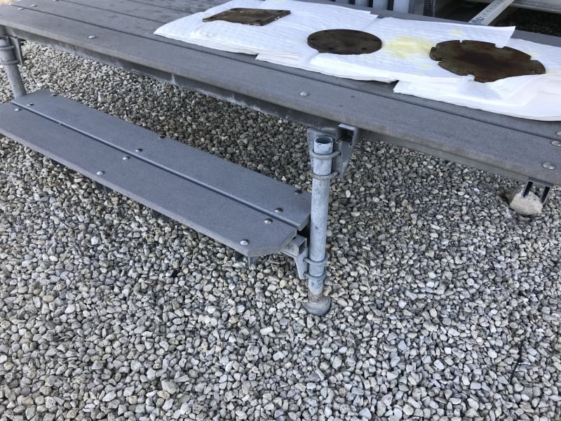
I was asked by a customer to see if I could calculate a load rating for a platform that they use while working on a piece of equipment. I have done this before on shelf or racks that we have built for him in the past but it is not really my specialty. This one has gone beyond my basic structural knowledge, they are using ubolt brackets to support the top of the platform to poles that are then set into the ground. I believe I will need to find the surface area of contacts and the force to find the friction, is there an easier way to estimate this?
uboltpic_yqvbfc.jpg
 
Replies continue below

Recommended for you

Is friction the only thing that holds the platform up in the air?

Any calc will be largely dependant of the tensile force in the legs of the ubolt.
Besides bad design, I wouldn't touch this with a 10-ft pole.

If anything, I'd suggest load testing, both of a single connection (x10 or something) to see what you're dealing with (order of magnitude), and when finished, a load test of the entire platform.

Isn't there a way to introduce positive locking (eg. a through-bolt through the column + the back plate) ?

---
 
Kingnero,I had the same thought when I saw the pictures, I don't want to touch this. I mostly wanted to see if this was something commonly done that I didn't know about. I can recommend modification which I think is the route I would go.

 
Drilling and tapping and installing a headed bolt to prevent slip of one or both of the U-bolts at each corner will at least help mitigate the poor design.

It is better to have enough ideas for some of them to be wrong, than to be always right by having no ideas at all.
 
Side load ratings for u-bolts already exist- for pipe support applications.

Example:


I also disagree that this is a 'poor design'.

It's convenient and fast to assemble, modular, requires only one tool for complete assembly in a pinch, and the failure mode for insufficient fastener tension is that the platform will start to slip as maximum loading is approached.

Once the tension on the u-bolts is high enough that slip is no longer the controlling failure mode, you're now relying on column strength of the tubes, and this arrangement is exactly as safe as any other design that uses the same column cross sections and bracing.
 
Kingnero,

The normal force created by the U-bolt depends on how tight the nuts are and the coefficient of friction between zinc coated steel.

If a torque wrench is used, the developed tension can be easily estimated. The coefficient of friction can also be obtained thru charts.

The contact area can be determined using fresh paint applied to the u-bolt and tightened. I will area will be approximately 1/16" x contact length

The developed slippage force is F = coeff. of friction x 2(developed tension of each u-bolt leg)

Hope this helps! ;)

aec062859
 
aec062859 (Mechanical) said:
Kingnero,

(1) The normal force created by the U-bolt depends on how tight the nuts are and the coefficient of friction between zinc coated steel.

(2) If a torque wrench is used, the developed tension can be easily estimated. The coefficient of friction can also be obtained thru charts.

(3) The contact area can be determined using fresh paint applied to the u-bolt and tightened. I will area will be approximately 1/16" x contact length

(4) The developed slippage force is F = coeff. of friction x 2(developed tension of each u-bolt leg)

(1): this is not accurately quantifiable.
(2): CoF will vary between almost zero upto 0.7 . Charts are basically useless in this case.
(3): As said above, why would you want to know the contact area?
(4): care to put an accuracy or tolerance on the value that you get using this method?


---
 
Under constant load, if the u-bolts are loose the step will start to slide but the u-bolts will drag and then catch - locking in place. Try it and see?
 
The above thread is a perfect example of CYA talking to the real world. Obviously CYA did not look at the photograph and realize that the catastrophic failure he envisions would result in a platform sliding at most 6-8"; the uses of this configuration are ubiquitous. Don't ever walk on a slippery sidewalk and entertain the danger of falling on your ass. Someone surely would have to be sued for it.
 
OBG - so partial failures and minor injuries are OK as a result of redneck engineering. As long as no beers are spilt or hound dogs hurt, I guess we're OK.

Real world, I wouldn't be the one to admit I built a step like that. Anyone can slap $h1t together out of hardware store parts.

It is better to have enough ideas for some of them to be wrong, than to be always right by having no ideas at all.
 
The capacity will be based on the coefficient of friction multiplied by the total clamping force, which is 2x the tension in both legs of u-bolt, or 4x the tension in each leg. The bracket is pressed against the pipe also, with equal force as the u-bolt is pressed against the pipe, each are equal to the total tension in both legs of the u-bolt. Edit: This ignores additional force of the legs of the bolt pushing on the pipe from the side, making this a conservative capacity calculation.

As long as the surfaces are clean when it is assembled, you should be able to use the coefficient of friction for the faying surfaces of slip-critical bolted connections. The AASHTO bridge design spec. has a design value of 0.3 for hot-dipped galvanized surfaces.

Determining the tension in the u-bolts based on the torque can be rather tricky, however. Friction on the threads is difficult to quantify and will significantly affect how much of the applied torque translates into tension on the bolt. In this situation, it's probably best to use a turn-of-the-nut method. This utilizes the lengthening of the bolt to determine the stress in the bolt. Stress = strain x E. In this case, the stress will be equal to the lengthening of the bolt divided by the bolt length, multiplied by 29,000 ksi. The lengthening of the bolt is equal to the number of total turns on the 2 nuts past snug tight, multiplied by the thread pitch. Be aware, the max strain before yielding is around .0027. The tension in each leg is then the stress multiplied by the cross-sectional area. If the bolts are tightened past yielding (which is generally acceptable), then tension equals the yield stress multiplied by the area.

Of course, if the pipe wall is thin enough and the u-bolts strong enough that the u-bolts deform the pipe, then the capacity goes up dramatically.

Edit no. 2: If the shear capacity of the bond between the galvanizing and the steel is exceeded, the effect will be noticeable, but minor slippage.
 
In real life the u-bolts are not purely horizontal. One of the beauties of this arrangement is that loose u-bolts hold pretty well. They become diagonal, see tension and grip.
 
Status
Not open for further replies.
Back
Top