Eng-Tips is the largest engineering community on the Internet

Intelligent Work Forums for Engineering Professionals

  • Congratulations waross on being selected by the Tek-Tips community for having the most helpful posts in the forums last week. Way to Go!

Weld Section Modulus

Status
Not open for further replies.

MDStruct

Structural
Nov 14, 2014
12
0
0
US
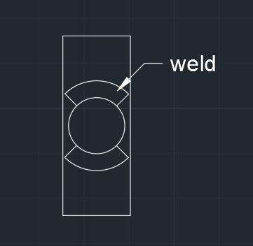
I am looking at the weld of a 5/8" diameter bar to a 3/4" bar post. Given the tolerances I know I can't get an adequate fillet weld all around. So my question is this, I am looking at Blodgett's book and his table showing the section moduli for different weld shapes. He shows the modulus for a circular weld, but is there any way that I could find the section modulus of two arcs instead of a full circle to account for no effective weld at the narrow sides of the connection? I have attached a quick sketch showing what I mean.

Capture_zbxjhr.jpg
 
Replies continue below

Recommended for you

I've no doubt that there's an equation out there somewhere. And we could surely derive our own given enough time. For production design, I'd just represent this as a pair of straight horizontal lines placed roughly at the weld centroids, one top and one bottom. The problem doesn't warrant any more accuracy than that in my opinion.

I like to debate structural engineering theory -- a lot. If I challenge you on something, know that I'm doing so because I respect your opinion enough to either change it or adopt it.
 
Or you could multiply the Sec Mod for a full circle by whatever fraction of a circle you've got.

Regards,

Mike

The problem with sloppy work is that the supply FAR EXCEEDS the demand
 
SnTMan said:
Or you could multiply the Sec Mod for a full circle by whatever fraction of a circle you've got.

I'm not so sure. This would produce a serious over estimate in the strong axis direction and a serious underestimate in the weak axis direction.

I like to debate structural engineering theory -- a lot. If I challenge you on something, know that I'm doing so because I respect your opinion enough to either change it or adopt it.
 
Regardless of actual relative strength of the weld in left-right and up-down axis (as drawn in plan view), a complete all-around weld will prevent corrosion underneath the weld and the joint.

In addition to that "better painted" (better plastic-coating ?) , it will be (over time) much stronger because of no "ends" of the continuous weld, rather than 4x "end points" of the two interruppted side weld arcs.
 
You can find section properties in ACAD. Draw it, make it a boundary, put it at 0,0 and find the secret properties icon.
Are you using the line properties method?
 
Sorry that I've been out of the thread. I have been busy researching calcs like this. I'm used to doing much larger scale design so going to small scale, fundamental stuff has been a challenging few months. Thank you all for your responses. I will actually keep this information in mind for next time. To provide some further insight....with the ok from my PE I ended up taking the S of a circle and assuming that approximately 1/4 of it is not effective. So I just used 0.75*S. This seemed reasonable since the ineffective weld occurs at what would be the lowest stress portion. This weld is simply the weld of a railing bracket to a solid bar post. So it has a moment which puts the highest stresses on the full weld portion.

KootK: That's a very good idea. Thank you.

racookpe1978: There will in fact be weld all around. Due to the geometry though, it's unreasonable to assume a full sized fillet all the way around. That is the reason I wanted to determine what the amount of effective weld is. The weld drawn in the sketch is what I assumed it to be. In the sketch the welds are cut off at 45 degree angles, but the actual weld is all around.

BUGGAR: Thanks for that. I didn't know that AutoCAD would do that for me. Yes, I was using the Blodgett method of considering it a circular line. (S=pi*d^2/4)
 
Railing post bases are notoriously difficult to design to allowable stresses using "standard" pipe and details. Let us know what you find.
 
As appot said,

You have this in CAD already, make the weld a "region" then get the "massprop" of the region to determine the moment of inertia. You can determine the section modulus form there.
 
I could have solved this back in 2nd year, but I think KootK offers a sensible engineering approach.
The error in his approximate calculation will probably be less than the variability in the finished weld, so it's "good enough".

"If you don't have time to do the job right the first time, when are you going to find time to repair it?"
 
Status
Not open for further replies.
Back
Top