Continue to Site

Eng-Tips is the largest engineering community on the Internet

Intelligent Work Forums for Engineering Professionals

  • Congratulations GregLocock on being selected by the Eng-Tips community for having the most helpful posts in the forums last week. Way to Go!

Weld Sequence 1

Status
Not open for further replies.

Joe591

Mechanical
Aug 21, 2020
49
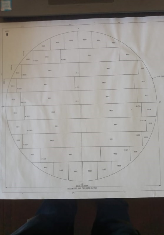
Busy building a tank and having serious warping issues with the tank bottom. What is the correct welding sequence for a tank bottom as displayed in the picture. You can almost say it's too late for this one as we are trying to see how we can push the part that warped upwards down with a crane or maybe we are going to put a generator on top of it to force it down, but it will be useful to know how we should have done it. The part in the picture fits in the centre of the annular plate. It's made of 10mm steel plate. The diameter is just over 20 meters

WhatsApp_Image_2021-12-09_at_09.37.02_ig8uqp.jpg
 
Replies continue below

Recommended for you


You should ask this question before welding commences. If you could adopt a proper welding sequence, the buckling could be controlled to a great extent .

You did not mention about bottom elevation measurements and hydrostatic testing of the tank.

I have API 650 11. th ed. and the clause 7.3.6.8 is below;

(Internal bottom elevation measurements shall be made before and after hydrostatic testing. Measurements shall be
made at maximum intervals of 3 m (10 ft) measured on diametrical lines across the tank. The diametrical lines shall be spaced at
equal angles, with a maximum separation measured at the tank circumference of 10 m (32 ft). A minimum of four diametrical
lines shall be used.)


I will suggest you to take measurements before and after hydrostatic testing and post the measurements within a new thread. My experience is that, most of the distortions would disappear after hydrotest.

Although API 650 specify to record buckling of the bottom plate , it does not specify any acceptable tolerance for the same.


I would remind the famous quote ( Don’t force it… Use a bigger hammer ...by ANONYMOUS )


Hydrostatic load will be more effective ..

I hope this respond answers yo your problem..

GOOD LUCK ..
 
I seem to recall that the drawing with all the notes states that we are not going to hydro it (for whatever reason). Design calcs were certainly done to API650. so were drawings, but I'm not sure to what extent we are following the code. The efforts with the crane failed completely because when you pushed it down the plate just popped up in another location again. We've cut some parts loose and we're going to have to trim some of the plates. If you look at the drawing above we started welding the horisontal welds from the top to the bottom. What I think has happened is each consecutive weld contracted a bit and now we are sitting with major shrinkage after the 4th one. I think we should have started with the centre horisontal welds and worked our way outwards. Can anybody give there thoughts on this.

 
If you can locate a copy of the Boilermaker Manual there is a section on bottom weld sequence. I'll try to dig up my copy...
 
@ifrs thanks. Sounds helpful. Ill have a look around for it
 
It's also possible that the root cause of your issue could be that your bottom plate was cut off of coiled material without a temper pass to remove the built in stresses from de-coiling. If so, the act of welding makes it sproing.
 
I found the boilermakers handbook. Very useful information inside. Adding it to my collection. The material is definitely much bigger than standard plate. Could be from coil. I'll look into it.
 
How serious are these warping issues? Any photos, dimensions?

Sometimes its just easier to accept them and fill in underneath.

What's the floor under the tank floor?

Don't know how you're getting away with not hydrotesting it? What product are you storing?

Remember - More details = better answers
Also: If you get a response it's polite to respond to it.
 
Floor under tank floor is tar. Under tar is concrete. Can confirm plate is def from coil.
Tank contains water. It could be that somebody else is doing hydrotest and we werent told. I am a mushroom. Kept in the dark.

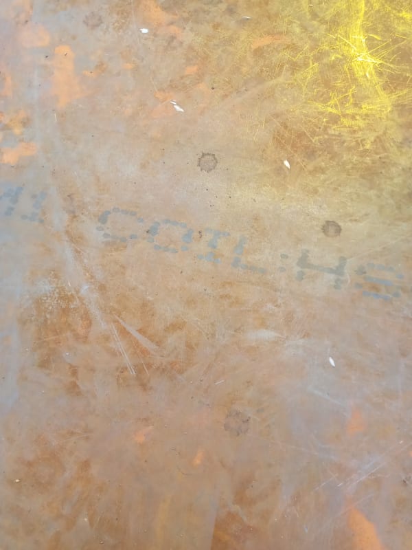
IMG_20211211_083714_ph3mci.jpg


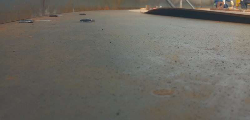
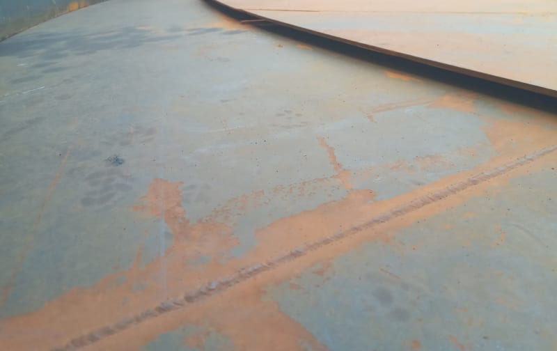
Photos of warpage:

IMG_20211211_084304_o1uz3u.jpg
IMG_20211211_084148_nvp7il.jpg


Its always a challenge to take photos and still make sure site cant be identified.

To be honest I think these warpages were caused by our strongbacks not being up to the task. We made them out of 10mm plate and they also warped with the plate. The 16mm ones we made later were much stronger and seemed to have prevented warpage further on.

Best suggestion ive had so far is welding dogs to the annular plate after the first layer of the shell is finished and wacking the warpage down with the combined effort of a heating torch, wedges and a 12 pound hammer.
 
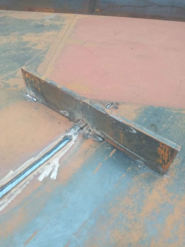
IMG_20211211_155724_qeafty.jpg


When I talk about strongbacks, this is what I mean.
 
How thick is the tar - is it asphalt road paving?
This is a butt-welded bottom?
What grade of steel in the bottom and annular ring?
What welding process is being used, are there backup-bars?
If these are butt-walds with backup bars, could the backup bars be sinking into the tar, cooling and then being trapped in the tar and then being restrained from moving?
 
Were using flatbar for backing plate. The bottom plates are just being joined by a root and cap stick welding process. The backing plate is just to keep the tar out of the welding, but it gets joined to the parent material good and proper. Was tacked to the parent material before the plates were placed. Never coming out ever again. Cant remember what grade steel it is now.

The tar is pretty soft still. But nothing is sinking into it by that much though. Its heat in the 10mm plates that created this mess.

Not sure what the thickness is of the tar. But its probably less than 60mm. Yes. Its the same tar you find on street roads.
 
How thich are the backup bars?

Not important but the weld in the strongback picture looks like a sub-arc weld.

I'm probably way off base but API has considered an agenda item for backup bars needing consideration for movement when on top of a concrete foundation. It's more for the foundation but I can see your backup bars likely being sunken into the asphalt and restraining the joints from moving, possibly being a contributing factor.
 
Do you know which seams they are welding first in each row?
Are they welding the short seams first?
 
we are using 30x3mm flat bar for backing plates. I don't imagine it should restrict the movemenet too much. We were welding straight across. The long welds first.Everything else tacked. Not sure what you mean by subarc weld? The strongbacks aren't welded by the main welders, they are tacked into place by semi skilled workers using single phase machines. The actual coded welders are welding all the main welds (the actual butt welds) with three phase machines. All in all it hasn't turned out too bad. The plates pulled mostly back into position when we continued welding. Had to do some minor trimming of some plates to get them to fit after everything shrunk into position. After that we only had minor wrinkling around the edges, but that we were able to hit into position with dogs and wedges. Busy finalising the welding over the next day or so. In the end it wasn't as much of a train smash as I thought it was going to be.
 
Status
Not open for further replies.

Part and Inventory Search

Sponsor