Continue to Site

Eng-Tips is the largest engineering community on the Internet

Intelligent Work Forums for Engineering Professionals

  • Congratulations cowski on being selected by the Eng-Tips community for having the most helpful posts in the forums last week. Way to Go!

What are the best locking methods for plastic parts? 2

Status
Not open for further replies.

DesEngineer4

Mechanical
Feb 19, 2013
181
Hello Everyone,

Hope All is well...

I'm working on a concept...I have attached my rough sketch (sorry, bad sketches). It has two parts PART -1(Base) and PART-2(Top). Part-2 will slide into the hollow section of part-1 and part-2 need to hold at three different heights (indicated as stage 1 to 3 in my sketch) to carry some load. I was stuck in selecting the locking method for holding the part -2 at required height. Initially, I thought to put some pins through the holes (from all sides) to hold part-2 but I'm thinking for a different and easy way to hold/lock the part-2 at required height. These are 3D printing parts (ABS Plastic).

Any thoughts/suggestions?

Any kind of help is appreciated...

Thank you..


Thanks & Regards,
Sam
 
 http://files.engineering.com/getfile.aspx?folder=c43dcf22-bdf9-42ce-8023-6a356456dbc0&file=IMG_20180211_193920_01.jpg
Replies continue below

Recommended for you

The sketches look like bumps on the inside part, holes through the outside part, which may be a decent way to go, depending on the actual part size.

Read up on snap fits to get started. In this case, you probably want conical bumps, because you need to slide them into and out of engagement during your staged assembly process.

They don't have to be circular; they could be obround.
Keep them away from the corners, where the walls will be extra stiff.


Mike Halloran
Pembroke Pines, FL, USA
 
Also, please remove all but one of your identical questions. Carpet bombing is not appreciated.


Mike Halloran
Pembroke Pines, FL, USA
 
I thought all are different forums..I will remove the same question in other forums..Thank you..

Thanks & Regards,
Sam
 
Posting duplicate questions starts multiple discussions, which is confusing, and wasteful of valuable time.

Mike Halloran
Pembroke Pines, FL, USA
 
I apologise Mike. I never duplicate again.. Thank you.

Thanks & Regards,
Sam
 
Actually, on my sketch those are through holes not bumps. I thought to insert long pins through it.. Again, I'm thinking these pins may cause the operator to change the position of the pins from one hole to another hole whenever he needs to change the height. That requirement of changing height of Part-2 will be frequent. So, I thought to ask for some suggestions from persons like you.. Is there any way to hold the part-2 in z-direction at desired height with simple mechanism and also it need to move from one height to another height. For example: operator set the height of Part-2 at stage-1 and do some work and after sometime he set the height of part-2 at stage-2 and do some work and repeats.. so, the locking mechanism at stages need to be simple and strong enough.

Thank you for your suggestion on snap fits. Will snap fit work good on a frequent changes? Also, these parts will be 3D printed. Is there any specific type of snap fit that works for my application? Please advise...


Thanks & Regards,
Sam
 
Yes, it's design requirements to be as boxes due to space constraint...

Thanks & Regards,
Sam
 
IMHO there is no "best" ... that requires an optimisation study between design alternatives that meet the design "must haves".

another day in paradise, or is paradise one day closer ?
 
Shanmuk44:
Without any sizes, dimensions, wall thicknesses, loads, etc. it is pretty difficult to know what to do. With plastic parts, the through holes and pins are somewhat suspect becuase all of the supported loads and manufacturing activity going on above are supported on a couple pins, at four bearing holes, but maybe only two bearing points until some yielding has taken place. The holes will elongate due to the bearing stresses and due to the repeated insertion of the pins. Finally, imagine the farting around of putting the pins into (through) the four holes each time you want to change heights. Also, how is part-2 lifted or lowered from one stage to the other? Can the worked do this by hand, or is it done mechanically, in some way? Finally, you talk mostly only about stages 1 and 2, but you show holes for 3 stages; and in fact there could be a 4th stage with the lower end of part-2 resting on the top of the base plate of part-1, so which is it? For the life of me, I don’t understand how you OP’ers. think you will get better discussion if you give the problem very little forethought, and then you give none of the pertinent design info. We don’t know if parts-1 & 2 are about 1" and 1.5" tubes or if you can get a couple people inside of part-2, and that could make a difference in a good, practical solution.

To get at least three stages of adjustment, I would start out with the bottom end of part-2 resting on the base plate of part-1. Inside part-2, I would have a set of two 1" high bearing blocks on the x-axis (one at +x and one at -x), almost as wide as the inside dim. of part-2. When these blocks are pushed outward against part-1 inner walls, and part-2 is lowered onto them, you are at your stage-1. Similarly, on the y-axis, but 2" high bearing blocks, with width smaller than above by double the thickness of 1" blocks, for clearance. Pushing these y-axis blocks to the inner walls of part-1, gets you to your stage-2. Now, one of the questions again, can we get people in there to set the bearing blocks or do we need a 1" long cylinder or mech. actuator? There may be some significant advantage to having part-2 be the larger tube, slipping over part-1. Now this bearing blocking can be accomplished from the outside, with different ht. blocks acting only on one axis, and just use 2" bearing blocks instead of 1" blocks at same holding device.
 
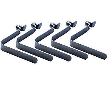
Could you use these spring detent things that you push in to allow the post to slide in or out?
71BVEWyThVL__SY355__acq0xs.jpg
 
"Yes, it's design requirements to be as boxes due to space constraint..."

So, they could be concentric cylinders, then. In that case, you could have pegs on the inner cylinder that ride a milled out channel on the outer cylinder that has detents for the levels you want to stop at.

TTFN (ta ta for now)
I can do absolutely anything. I'm an expert! faq731-376 forum1529 Entire Forum list
 
Status
Not open for further replies.

Part and Inventory Search

Sponsor