Continue to Site

Eng-Tips is the largest engineering community on the Internet

Intelligent Work Forums for Engineering Professionals

  • Congratulations KootK on being selected by the Eng-Tips community for having the most helpful posts in the forums last week. Way to Go!

What are the drawings presented for a post-tensioned slab ? 2

Status
Not open for further replies.

JDG3718

Structural
May 13, 2017
25
Hi, I have a post-tension slab I want to draw it in autocad but i don't know how many plans to present and how each plan layout, can anyone present any sample autocad or pdf showing layout of slabs presented by a company or office ?
 
Replies continue below

Recommended for you

I assume you are producing such plans as an consulting engineer on a project.

Practices vary around the world. In the North America (and the US specifically) the EoR produces a PT design drawing that shows high and low points, forces, and a general layout, then the PT supplier will produce PT shop drawings that meet that design. In other parts of the world the consulting engineer will detail the PT fully - number and spacing of tendons, rebar T and B, sometimes formwork profiles too.

Where are you practicing and what do your colleagues do?
 
Actually I am a civil engineering student so I am doing this by myself, and unfortunately not for a university project (they don't teach prestress), I usually use metric system and in my country we follow all american codes and layout. If you mind, could you send some documents about how to detail such a slab ? I already ran the analysis in SAFE but I never actually drawn a post tension slab before I saw how detailing in SAFE is but it is not very much good. Thank You for your reply.
 
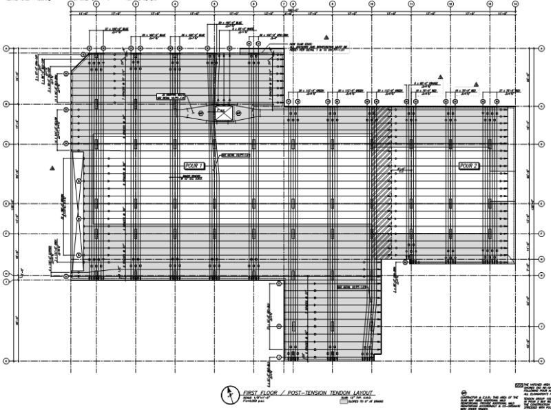
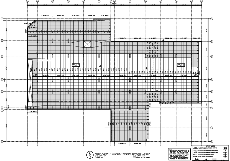
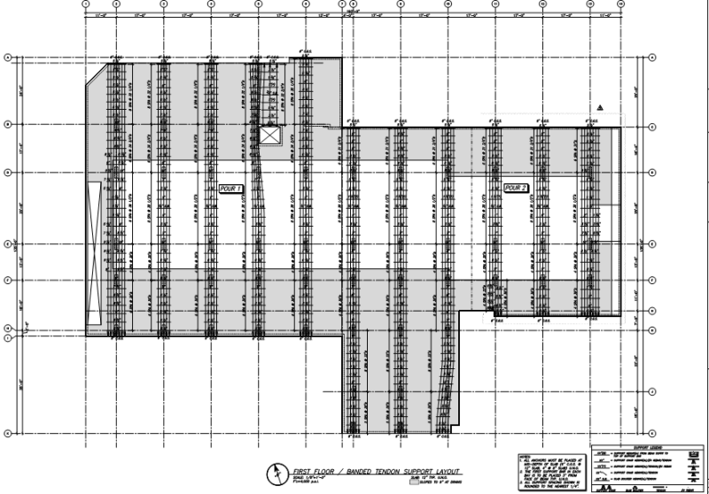
Typically, in North America, besides typical notes, general details, specific details etc, the main three drawings produced by the PT supplier/installer are TENDON LAYOUT drawing, DISTRIBUTED TENDON profiles, and BANDED TENDON profiles, as follows:

Capture_layout_htttng.png


Capture_distributed_x6bpg9.png


Capture_banded_nze1qp.png


The structural engineer will first produce design drawings that show the general PT arrangement, high/low profile points, forces etc., and top and bottom rebar etc. The PT supplier/installer will produce the shop drawings based upon the engineers design drawings and project specifications.
 
Ingenuity:

Any chance you can repost the drawings in a scaleable format. When I zoom in to see the notes, the 'jaggies' totally obscure the text.

Dik
 
dik:

Will do. But I have to first modify the PDF files to delete the title blocks etc - project the 'guilty'.

FYI - I was was NOT the EoR on this project - we just did the PT repairs consisting of de-stressing, de-greasing, re-greasing and re-stressing of several hundred tendons to a 6 year old structure. Long story.
 
See attached PDF file. 3 PT shop drawings total. This is a PT podium deck supporting 5 levels of cold-formed steel framing.

FYI - standard US PT detailing/symbols used, so legend for tendon symbols is:

Capture_ugcb0h.png
 
Ingenuity:

Thanks very much... Dik
 
Status
Not open for further replies.

Part and Inventory Search

Sponsor