Continue to Site

Eng-Tips is the largest engineering community on the Internet

Intelligent Work Forums for Engineering Professionals

  • Congratulations IDS on being selected by the Eng-Tips community for having the most helpful posts in the forums last week. Way to Go!

What could be causing these nuisance ground fault trips at the mains of the switchgears?

Status
Not open for further replies.

bdn2004

Electrical
Jan 27, 2007
794
We have two of these units installed on two switchgears fed from the same Power Distribution transformer. Both are monitoring (via a CT) all 3 phases and neutral cables on load side of a 1200A Pringle switch main(w/shunt trip) in each gear.

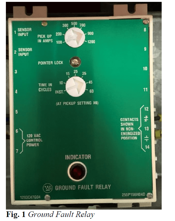
We have been experiencing ground fault trips on each of these relays, 2 - 4 times per year over the last couple of years. Sometimes both relays trip, sometimes just one side. With the absence of any apparent damage, and by meggering all cables, we’ve pretty much eliminated that these trips are being caused by an actual ground fault. We’ve also checked all wiring and connections for the GFR system and all checks out okay. Each GFR is set at 900A, 45ms.

My question is what could be causing these nuisance trips? I’ve read a little about charging currents and third harmonics causing issues. Could this be the cause of these trips? I noticed the new digital GFR’s have protection or filters for third harmonics. Would you recommend replacing these old units with new digital units? Do you have any other ideas?
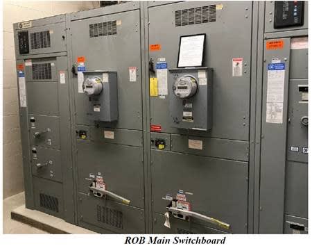
Rob_Main_Switchboard_ssadqz.jpg
 
Replies continue below

Recommended for you

Two questions please.
1) You have mentioned 45ms tripping time. But the relay setting is in 45cycles. That means only 2cycles which is too short to pass transients. Which is correct?
2) The relay shows TRIP TIME IN Cycles @ 6xPICKUP. Since the pickup=900A, does that mean that there should be a GF current of 900x6=5400A to trip the relay
in 45Cycles or otherwise? The manual will clarify it.
 
TCC's of this ground relay are typical,i.e. the operating time is constant when the fault current is above the PU setting. The X6 note is odd. It mostly applies for long delay time setting... for phase protection not ground.

We did have some problems with loose conductors going into the z ct.: just a slight movement of the cables was enough to trip the thing.
They were too long and were resting on the back cover of the gear. Only pushing the cover would trip the entire facility.
 
30 years ago I saw false trips on similar "W" units when large chiller motors with wye-delta reduced voltage starters transitioned from wye to delta.

Another installation had unsymmetrical arrangement of conductors in the zero sequence CT. It looked like large currents would saturate a portion of the rectangular CT and cause an incorrect summation of the unbalance sensing curren, causing a false trip.

One square zero-sequence CT was positioned too close to another bus. Multiple motor starting currents appeared to affect the portion of the CT closest to the other bus and give an incorrect summation current to the relay.

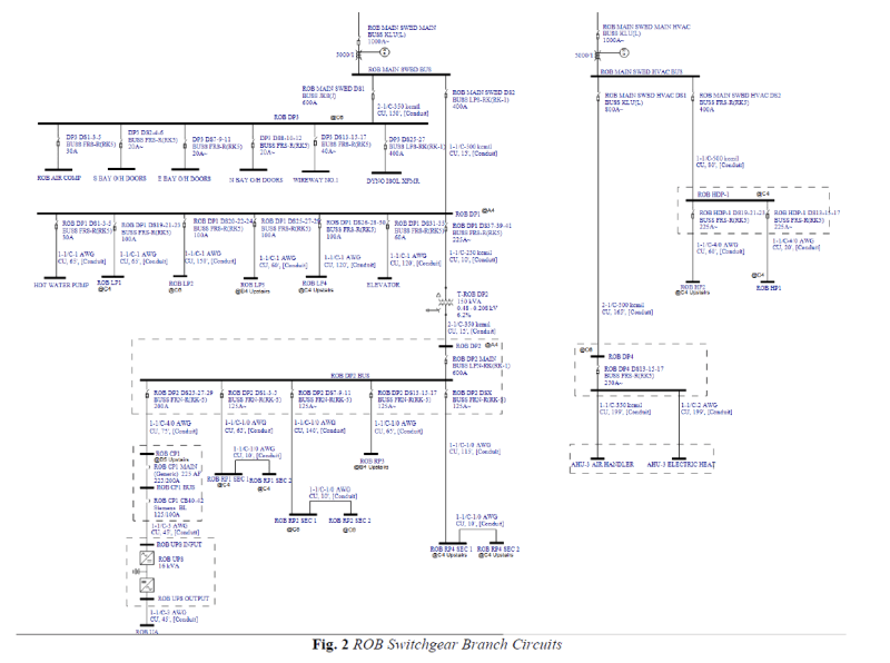
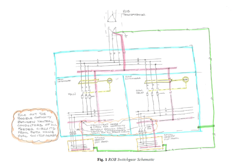
Downstream neutral inter-connections might allow neutral current to return to the transformer though the other CT, causing a false trip on high momentary currents. The same thing could happen if any neutral is grounded downstream.

Bob Wilson
Retired EE
"Don't let the smoke out!"
 
Two questions please.
1) You have mentioned 45ms tripping time. But the relay setting is in 45cycles. That means only 2cycles which is too short to pass transients. Which is correct?

It is cycles...

2) The relay shows TRIP TIME IN Cycles @ 6xPICKUP. Since the pickup=900A, does that mean that there should be a GF current of 900x6=5400A to trip the relay
in 45Cycles or otherwise? The manual will clarify it.

Not sure what 6X means either..
 
Time delay is 45 cycles. That's 750 ms at 60 Hz. The pickup is 900 A. Per NEC, 1200 A is the maximum setting.
 
Status
Not open for further replies.

Part and Inventory Search

Sponsor