Continue to Site

Eng-Tips is the largest engineering community on the Internet

Intelligent Work Forums for Engineering Professionals

  • Congratulations KootK on being selected by the Eng-Tips community for having the most helpful posts in the forums last week. Way to Go!

What does a Roller (beam to beam) Steel Connection looks like?

Status
Not open for further replies.

PPoyyyy

Structural
Mar 22, 2017
6
So i have to design the stairs and i decided to make the end of the stringer a roller connection . But i received a drawing and i didn't know what to make of it:
Untitled00000000_rmqkmr.png

I know i'm gonna sound like an idiot here but i'm new ...So what does a Roller beam to beam connection really look like? ...And Thanks alot for any help!
 
Replies continue below

Recommended for you

Usually when you assume a pin or roller connection at a joint, it is not actually going to be a "true" pin or roller in reality. There's going to be some sort of fixity or resistance in almost any connection because it is integral to an entire system that can resist forces in ways that engineers don't account for in order to simplify design. In this case you designed that connection as a roller, therefore assuming that there was no horizontal reaction at that connection. This is a correct assumption in this situation since your stringer is connected into a wide flange beam where any horizontal force on the beam is acting in the weak axis, where the beam will have little stiffness to counteract this force. If you designed the stringer with adequate stiffness, meaning it is within deflection limits, the horizontal deflection at the joint will be minimal. The connection shown is fine for this application, if you want to be sure about it you can calculate the horizontal deflection at the stringer/beam joint and make sure the beam won't yield under that deflection.
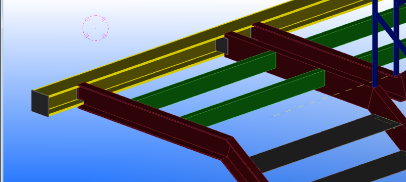
 
In practice, the default position is to assume that all beam supprorts are incapable of providing axial restraint unless there's a compelling reason to think otherwise. So most beam support connections are idealized as rollers from a structural modelling perspective.

I like to debate structural engineering theory -- a lot. If I challenge you on something, know that I'm doing so because I respect your opinion enough to either change it or adopt it.
 
If you are concerned about the stiffness of the stringers acting as vertical braces, and attracting forces that should be going into your lateral force resisting system, you can also provide slotted bolted connections at either end of the stringer. The length of the slotted holes should be twice the maximum anticipated inter-story inelastic drift.
 
Practically speaking, a roller connection looks a lot like a pin connection unless you provide some mechanism for the support to slide such as slotted holes, a sliding (Teflon) plate, etc. (It is easier to distinguish between a roller connection and a moment connection, as a moment connection usually involves beefier connections of the beam flanges.) For stair stringers, you can model the top of the stringer as pinned and the bottom as a roller where the stringer is in contact with the floor or ground.
 
Bolts in horizontal long slots. Perhaps extra long slots if your anticipated movement is longer than a standard long slot.
 
Status
Not open for further replies.

Part and Inventory Search

Sponsor