Eng-Tips is the largest engineering community on the Internet

Intelligent Work Forums for Engineering Professionals

What does this mean?

Status
Not open for further replies.

R1chJC

Marine/Ocean
Apr 15, 2015
51
0
0
GB
Hi All,

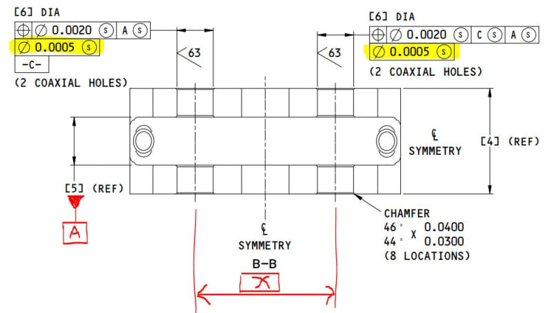
Can anyone help me interpret the drawing below. I've no idea what that second FCF row means?

I'm re-drawing the part and am trying to decide if what was originally drawn is the best approach (I've added stuff in red for clarity that's on another view)

I already have issues with "symmetry" being written...

I'm drawing to the newer ASME so have dropped the (S) modifier.

From a design perspective i don't mind if the holes drift as a pattern as long as they remain co-axial and square to datum [A] (bolts go though the holes).

Capture_yq3vdw.jpg
 
Replies continue below

Recommended for you

I am at a loss to imagine what was meant in the secondary FCF. A diameter symbol? Unless that's meant to control the feature of size with a .0005" tolerance, but if that's the case, the diameter dimension should be directly toleranced and the location dims for those holes should be basic. Also, the formatting is off. There should be no leading zero on the tolerance in the FCF, the diameter dims should have the same number of places as the tolerance and I see no reason to include the fourth place in the .0020 tolerance. I believe it should be a diameter of 6.0000±.0005 size and a basic [X.XXX] ±.002 for location.

There may be other issues with this but I'll let someone else take a whack at it first.

I'm not a vegetarian because I dislike meat... I'm a vegetarian because I HATE PLANTS!!
 
That whole drawing makes my head hurt. Are the dimensions in square brackets like [6]DIA supposed to be basic? If so then why do some of them have (REF) after them? Looks to me like the whole thing was 1) produced to no known standard and 2) produced in something other than a mechanical drafting package. I suspect who ever made it does not understand GD&T and does not know what they want. Good luck reading their mind!

If I had to take a wild off the wall guess I'd say the second frame is meant to be either a roundness or cylindricity control given that there are no datums.

----------------------------------------

The Help for this program was created in Windows Help format, which depends on a feature that isn't included in this version of Windows.
 
You're giving the author a little too much credit perhaps dgallup. ;-)

I suspect, based on the level of proficiency with symbology and layout that they thought they would control the size of the hole... That's my guess! I'll bet $2!

I'm not a vegetarian because I dislike meat... I'm a vegetarian because I HATE PLANTS!!
 
Another questions, if I make both holes relative to [A], does it evoke a simultaneous requirement and control the symmetry of the two holes about the centerline?


Capture2_kb7aze.jpg
 
These type of wannabe drawings make my head hurt also!
I have seen these type of drawings come from Program Managers, Sales, etc. They think they have it right based on other drawings they "interpreted".
It looks like they are trying to control the location of the hole .0020 to datum A, and the size of the hole .0005, regardless of size (s).

Chris, CSWP
SolidWorks '17
ctophers home
SolidWorks Legion
 
I'm not fully familiar with the term "simultaneous requirement" but what I can say is that it looks like you're controlling the position of the holes to A+B, to .002, and further, are refining the perpendicularity of the holes to A to within .0005. That's probably not entirely correct, but it's a little difficult to read this print for me.

I'm not a vegetarian because I dislike meat... I'm a vegetarian because I HATE PLANTS!!
 
R1chJC,

If both position callouts reference |A|B| in the same order of precedence and in the same boundary condition (RMB) as shown then yes that would be simultaneous requirements. Though I'm not really sure why you wouldn't just call it out as a pattern of 4x holes if they all are the same size and held to the same size tolerance zone.

*Position to |A|B| will hold them to tolerance zones each located half of your basic distance [x] from your center line (plane? looks more like a center plane) generated by datum feature B so it will be symmetric in that sense.


*Edited for clarity.
 
Just as an additional note, as you have it shown (two separate callouts subject to simultaneous requirements) the lower segments of each composite tolerance are not subject to simultaneous requirements by default. There is some debate as to what simultaneous requirements for the lower segment of a composite tolerance means exactly - I won't get into it, suffice to say that if you indeed want to hold the patterns with simultaneous requirements instead of a 4X pattern as I suggested, I would highly recommend switching to Multiple Single Segment position instead.

Note that the lower segments of a composite tolerance are held in relative orientation only to the referenced DRF, so they would float freely within the larger zone dictated by the upper segment.
 
Status
Not open for further replies.
Back
Top