Continue to Site

Eng-Tips is the largest engineering community on the Internet

Intelligent Work Forums for Engineering Professionals

  • Congratulations GregLocock on being selected by the Eng-Tips community for having the most helpful posts in the forums last week. Way to Go!

What happens if you don't transpose the ground conductor? 1

Status
Not open for further replies.

psmpsm

Electrical
Dec 19, 2022
35
I'm working on a project where the customer is pulling 1/C #750 through conduit in flat formation, underground in a duct bank via single point bonding. So each phase is in a separate conduit.

IEEE 575 says to transpose the ground conductor at the midway point if using single point bonding. However, the project says they might not transpose the ground conductor at all.

Does this affect induced voltage?
 
Replies continue below

Recommended for you

It may.
Transposing will not avoid induced voltages but it will effectively cancel them out if done correctly.
Mid point for single phase systems. (Two equal sections to cancel.)
Two intermediate point grounding for 3 phase systems. (Three equal sections to cancel.)


--------------------
Ohm's law
Not just a good idea;
It's the LAW!
 
^^Did you respond understanding that we are talking about transposing the ground conductor here? I wasn't talking about transposing the phase conductors.

I don't believe transposing the ground conductor cancels out induced voltage, as I have calculated the induced voltages for these cables and they are not zero.

IEEE 575 does show what happens for multi conductor cable if the ground conductor isn't transposed, and what happens is that the induced voltage doubles. However, they provide no calculation backup for that, and I'm not quite sure the same applies to single conductor cable.

I have searched everywhere for a whitepaper that talks about this but I'm unable to find anything.
 
A voltage will be induced in a nearby grounding conductor. The relative phase angle of the induced voltage will be related to the current causing the induced voltage.
If you had calculated the phase angles of the induced voltages of a properly transposed grounding conductor and summed them with regard to phase angles you will have seen the cancellation.

--------------------
Ohm's law
Not just a good idea;
It's the LAW!
 
The concern is what happens to the induced voltage on the phase conductors though, due to presence of the grounding conductor. I understand your comment regarding the phase angles cancelling out on the ground conductor - but how does this affect the phase conductor induced voltages, with respect to transposition vs no transposition?

Are you saying that without transposition of the ground conductor, the phase angles will not cancel on the ground conductor, thus creating a higher circulating ground current, which leads to higher voltage induced on the phase conductors by the ground conductor?
 
Long phase conductors are subject to induction and capacitance.
The magnitude of these effects is influenced by their orientation and spacing to each other and to ground.
The effects are seldom equal between phases and can cause unequal impedances on the different phases. Differing impedances May cause differing voltage drops and differing phase angle shifts.

Grounding conductors. When a voltage is induced in a ground conductor by a parallel phase conductor, the voltage is proportional to the distance. Proper transposing of a three phase circuit will result in a maximum induced voltage at any point on the conductor of 1/3 the end voltage of an untransposed conductor and will result in zero Volts at the end of the run.

Consider:
3 x 2/0 AWG in each conduit.
Three phases in each conduit.
1/3 ampacity grounding conductor in each conduit.
You will avoid the possible unequal impedances that the original scheme may cause.
You will save almost 1/2 the copper.
You will avoid possible magnetic encirclement.
The induced voltage on the grounding conductors will be negligible.
One phase in each conduit is bad practice and should be avoided whenever possible.

I hope that your conduits are non-magnetic.
Magnetic encirclement is a serious issue that may arise when your cables enter any enclosure constructed of magnetic material.
I have seen a 400 Amp disconnect destroyed by heat generated by magnetic encirclement.
I was told that the switch failed regularly and was replaced every year or so.
The maximum load was under 200 Amps.


--------------------
Ohm's law
Not just a good idea;
It's the LAW!
 
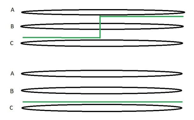
Yes, the conduits are non magnetic. The cables are single conductor #750 so I'm assuming because of the size and also due to pulling tension they are pulling the cables in single conduits. I get what you are saying in relation to transposition; however I can't make sense of what actually happens from an induced voltage perspective. Simply, the following picture is what I'm trying to figure out.

Transposition_zs0tqb.jpg


The equipment continuity conductor (ECC) is in green. Top is transposition (midpoint), bottom is not.

For a single line to ground fault, assume the induced voltage across any phase is 20 volts/meter.

If you analyze the untransposed diagram , does that 20 volts/meter increase, and if so, by how much?

IEEE 575 has an example on this where the induced voltage doubles without transposition, but that is for multi conductor cable. It says nothing about single conductor.
 
Status
Not open for further replies.

Part and Inventory Search

Sponsor