Hey all,
I agreed to help a neighbour install & commission an industrial lathe driven by a three-phase 550V motor. His wiring is excellent...but the equipment he's using to supply it is a mixture of new & used...
Rotary phase converter output has been wired to a three-phase single-throw disconnect switch, enabling the RPC to be started without any connected load, as specified in installation instructions; so far, so good...I think.
P-P RPC output voltages as measured were [if I recall correctly] ~240, 265 & 270 volts with disconnect open.
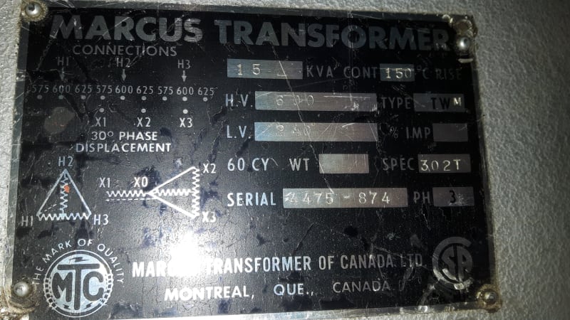
Now here's where it gets interesting, and I wish I had had time to take some nameplate pictures, as the step-up trafo is T wound on both the LV and HV sides; P-P output between two of the HV terminals [I measured at the ones labelled 575V] were ~590V, and the other two were >600V [unfortunately my digital meter won't read higher than that]. In lieu of those numbers I also went P-G and got - again, if I recall correctly, ~350, 380 and 400 something.
I realize more info may be needed, but the question I have is, should the real output of the RPC be connected across the cross-arm of the LV Tee, and the two derived connections go from each of the two ends of the cross-arm down to the base of the stalk? Or the real voltage applied from one of the two ends of the cross-arm down to the base of the stalk?
I also intend to see that the lathe control circuitry gets connected across the realest two phases that show up at the lathe.
I still plan to take some pics to post here, as I ran out of time yesterday.
Thanks for any recommendations.
CR
"As iron sharpens iron, so one person sharpens another." [Proverbs 27:17, NIV]


