Continue to Site

Eng-Tips is the largest engineering community on the Internet

Intelligent Work Forums for Engineering Professionals

  • Congratulations waross on being selected by the Eng-Tips community for having the most helpful posts in the forums last week. Way to Go!

What is the lateral resisting system of this structure? 2

Status
Not open for further replies.

Said the Sky

Structural
Oct 1, 2018
73
1D47D0D2-84E7-46F5-8F34-F49CC77FCED3_kwdrd4.jpg


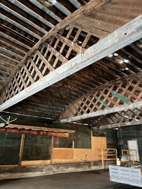
Hello gentlemen,

Background on the building:

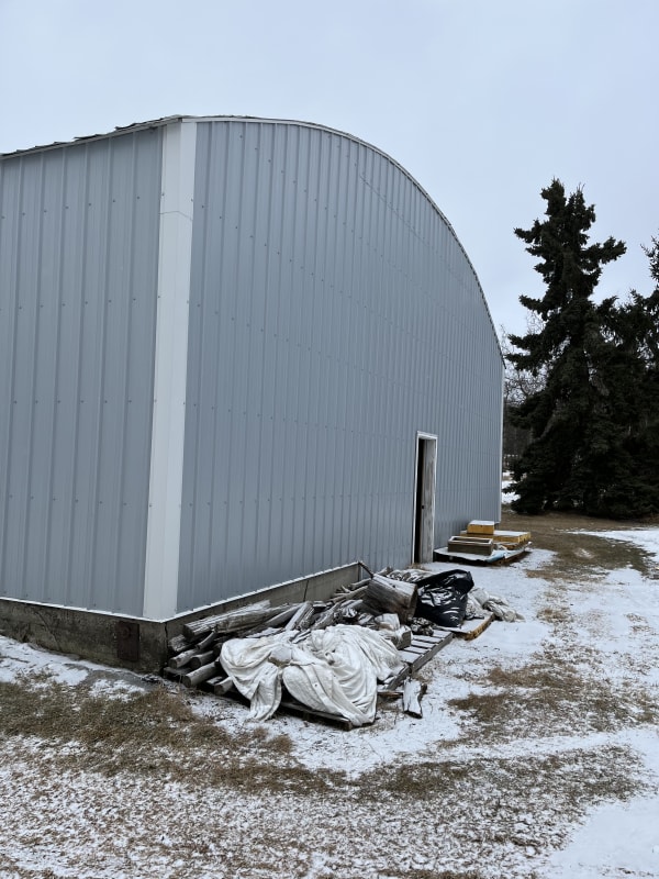
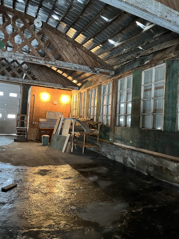
Foundation appears to be concrete wall perimeter about 4ft high, should be on strip footings, SOG. Building used as “agricultural” purposes.

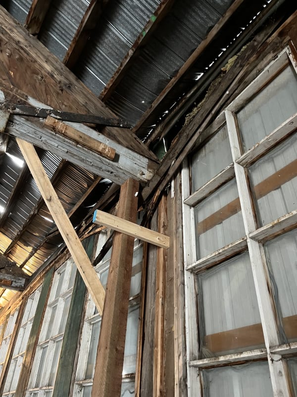
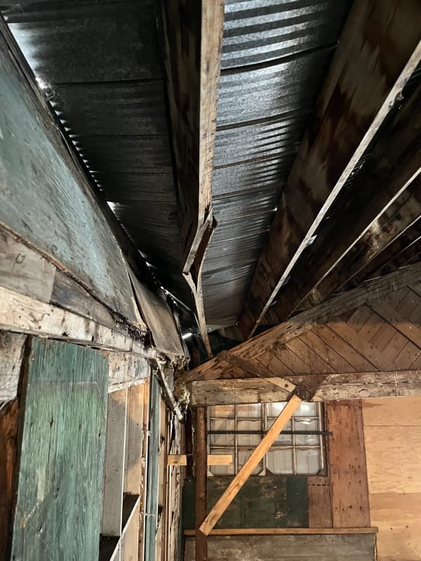
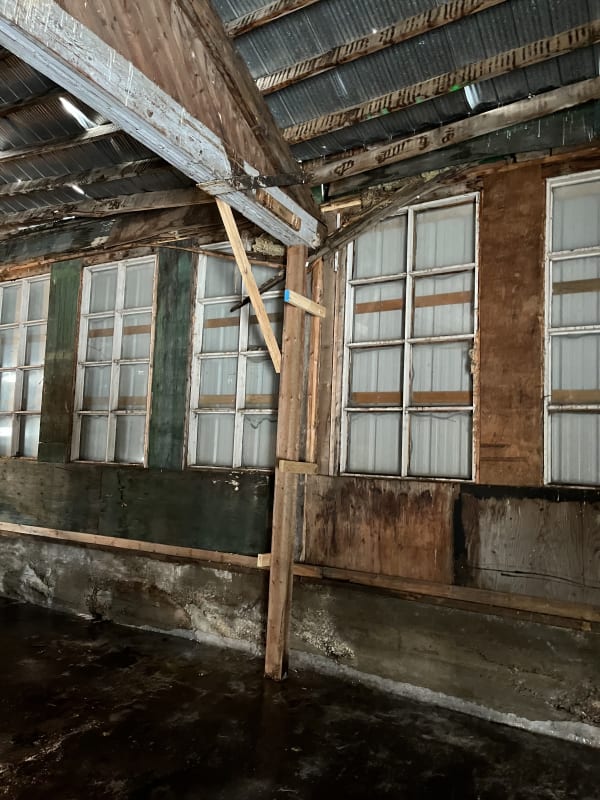
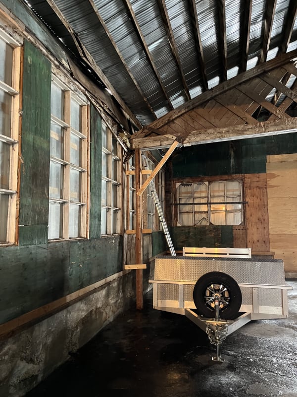
The building has since have a partial collapsed in high winds and high snow loading (2.5ft of snow). The failure however is those big arched trusses, one of them has fallen off its stud pack support. The top sill plates appear to be rotted but I do not believe this to be the main reason the truss fell off its post support.

I think this building has no later load resisting system. The truss and post are not built as moment frames. The posts are stud packs and do not appear to be moment connected into the ground to provide lateral support. No knee bracing for moment frame action.

So my thoughts are the sheet metal is transferring the horizontal wind loads to the wall and thus pushed the truss off the post support.

Anybody has any ideas if my assumptions are correct?

Thanks!
 
Replies continue below

Recommended for you

I think you are correct. It is called 'trickle theory'.
 
thanks Hokie, could you please elaborate what you mean by trickle theory?

on another note: are you familiar with these farm structures? are they usually built with cantilever fixed columns at the base for their lateral resisting system? I feel like knee braces to create moment frames are usually not correctly detailed for the connections to work, what I usually see is a few nails at these locations that connect the knee brace to the column and then to the truss, seems like it won't be stiff enough to do much of anything.
 
I'm not an expert on farm structures, but know they sometimes fall down. By 'trickle theory', I just mean there is no well defined load path, so the forces just trickle through whatever structural or non-structural elements are available, until they don't.
 
The roof to the side walls and endwalls... for whatever resistance they have... You might want to look at how they are connected. It looks like the ends are 'filled in' to tranfer the higher shear and the reduced depth.


Rather than think climate change and the corona virus as science, think of it as the wrath of God. Feel any better?

-Dik
 
Hi dik, I had considered that was a potential case too but the length of the building is 60ft with only three of those trusses inbetween, so about 15ft spacing of trusses, even if the end walls are the lateral resisting system there is too much load to transfer over a 60ft span. The end walls have metal sheeting which could drag the shear into the foundation wall, but no overturning anchors could receive this kind of load into a 6” thk foundation wall without some kind of concrete break out to consider. If it was a pedestal if some sort I think could be justified.

Also the 60ft span for diaphragm the deflection could be high enough to justify my conclusion that the deflection pushed the truss off its support.
 
It's sometimes difficult to determine why something is standing when, by rights, it should collapse. About 20 years back, I did an investigation about a total building collapse that may have been precipitated by an employee leaving and the added pressure from him slamming the door may have been the contributing factor; it was that close and the only way I could justify it standing was using actual Euler buckling of chord members... they were way beyond code... due to improper bracing. Tension members were braced.

Rather than think climate change and the corona virus as science, think of it as the wrath of God. Feel any better?

-Dik
 
Said the Sky said:
are they usually built with cantilever fixed columns at the base for their lateral resisting system?

In my neck of the woods we call these pole barns. Because they take big poles, sink them into the ground until they develop enough fixity and stability, and then build a roof on top and some walls if they're feeling fancy (or have a really nice tractor).

That doesn't appear to be the case here, though. I think dik's right that you're getting diaphragm action out of the roof system to the end walls. That's about the only logical path. Just because the materials aren't connected the way we want them to be or the materials aren't 'rated' for the load doesn't mean they can't do the job - we just don't trust them to if people will occupy the building. And by "the job" I just mean standing up - don't try to attach a capacity to it. Think of it like a dining room table. Slab of wood with four sticks pegged into the bottom a half inch. Is that moment connection? Absolutely not. But can you sit there and lean on it and eat dinner every night for 20 years without it falling down? Yes.

I must say - that's a neat "truss" design...like a bowstring full of lattice. Any chance you got a good full length shot? I'd like to see the whole thing.
 
I have seen endless examples of these old farm bldgs without a clear load path. One project I recall my boss at the time thought it was hilarious when he overhead me ask a potential client, "you want humans to live there?" Needless to say we walked away from that project. There is one I drive by frequently that has been up since the 50's. Every year you can see the roof sag a little more. In your case I would look at the connections between the web material and the chords of the bow strings. Some of the home built trusses I have looked at used 1"x_ material with very long unsupported lengths and 2 or 3 nails at the joints. Keep in mind they did not have air nailers when this was built. Here it appears you only have webs on one side.

I would ask what is your role? Unless someone has deep pockets or this is a historical building I would be very cautious before getting involved.
 
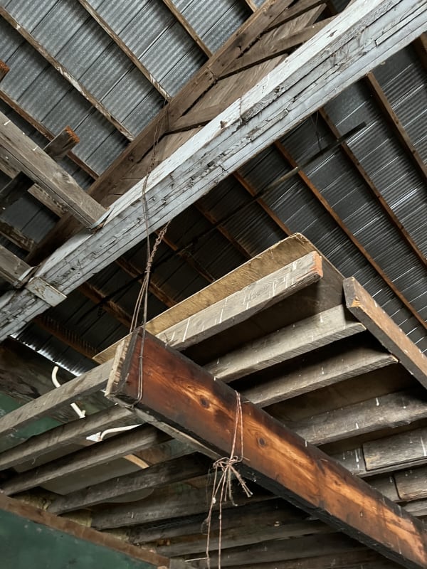
Searching for images, I learned that this is called a 'Belfast Truss'. It looks to me like it had some diagonal braces removed at the columns. (Maybe these were inconvenient to wall/window infill)
 
I love it. The masochist in me wants to show it to a few architects...
 
For the question: “what role am I taking” Im a forensic engineer with structural consulting background. The owner wants to get the money from his insurance to repair. The insurance has their own structural engineer.

Owner wants to determine the cause, wind or snow so he can get paid out. But from my opinion if this was built right it wouldn’t have had the partial collapse. I don’t believe there was any cross bracing, nor any anchors/tie downs from the post to the wall. I believe it is relying on trickle theory as Hokie mentioned, and the fact that 1 in 10 year winds finally reached the loading to make this building fall.

In Canada the farm code is very relaxed, seismic doesn’t need to be checked, wind loads are lesser than the building code. Farm buildings are excempt from the code also, which is why we probably see a lot of “do it yourself” farm sheds.

I’ve added more pictures for your entertainment
E26356A2-4D73-4D8F-B061-B9FFFAD9DC48_specs8.jpg
7A6E2332-0AA5-493D-8862-B7AED2AFA01B_hjulbk.jpg
05F180D2-A67B-4022-A137-08B03350D884_zkbvkc.jpg
 
Question #2: Does their insurance policy have a clause about latent defects? If so, this will go poorly. You could be swimming upstream.
 
I think kipfoot is correct. Someone removed the braces. The bottom chords are missing paint where they used to be.
 

or maybe the comedian? Just to give them a few ideas that they can use in future? I should have added, "and improve on in future." [ponder]

Rather than think climate change and the corona virus as science, think of it as the wrath of God. Feel any better?

-Dik
 
I think kipfoot and jorton is right, it looks like all trusses have missing paint here that shows a brace use to be there. removing this brace could increase the slenderness of the posts/stud pack supporting the belfast truss and thus buckles under snow weight and or wind loading. I did some searching of belfast truss and it seems not all belfast has those braces though. Here is some closer pictures of the painted area.

this one truss slipped off the post and is temporarily braced by the 2x4 and 4x6 post, how they put the post up in time is beyond me.

IMG_0509_ayxzu4.jpg
IMG_0514_ddxzbw.jpg
IMG_0503_wlwkj7.jpg
IMG_0567_kvpmid.jpg
 
I'd like to make a comment but I think that there should be a photo of the top of the post where the damage is at. You may find a lot of dry rot. It appears that the exterior siding is much newer than the internal framing. Interesting trusses - probably no horizontal thrust at the posts. The sheet metal/plastic clear corrugated roofing is suppose to work as a diaphragm and transfer the wind loads to the end walls which will have to take the shear loads down to the wall footing. Big members for the chords but looks ok if the splices are adequate. The end wall shear loads are probably resisted by the sheet metal siding which you may find some load values in a catalog if the stud spacing is known. The loads eventually have to be transferred to the studs by nails - messy analysis and may not begin to figure. Check for hold downs at the end of each shear panel and foundation bolts for sliding.

Note the metal siding covers all of the original windows at the walls. Kind of neat. Try to find out who did the recent remodeling and whether there was an engineer involved.

A comment about when something should fail. The actual failure is probably near the allowable stress plus about the factor of safety.
 
Said The Sky said:
Owner wants to determine the cause, wind or snow so he can get paid out. But from my opinion if this was built right it wouldn’t have had the partial collapse.

Might have been better for the owner to have lit a fire - either way it is fraudulent.

 
Hi Old runner I had originally assumed the same load path as you originally, but the length of the building is 60ft long, so to transfer all the loads through diaphragm action of the roof to the end walls that gives a high overturning moment which I think any holddowns should be checked for concrete break out on such a thin wall (6" wide concrete foundation wall). unfortunately i dont have access to check what hold downs are there, and I doubt any engineer designed this (probably a do it yourself project). This could maybe be by-passed by using a embed with welded rebar and proper development length but I highly doubt this is the case. If the roof is a diaphragm and does transfer the shear to the end walls the deflection would be too high a midspan and thus those trusses may move over time, over 50 years we can see those trusses shift and eventually combined with the wood rot lost its bearing and thus the owner may have seen that happening and put a temporary post and brace in there.

I think the other poster are correct also in that the knee brace was removed, so its not longer a moment frame action, thus allowing movement over time.
 
Actually what you and I described is what happens - or suppose to. But the diaphragm action probably doesn't really work very well and there is probably big deflection with big winds - have to be there to witness it. This is probably not going to be a retrofit but I think your job might be to provide what broke and getting up to the top of the post in the area of the collapsed area will be very helpful. Probably can install diagonals tie rods under the trusses (like a standard industrial building. The depth of the diaphragm is pretty good - may 30 to 40 feet? I don't think your client is looking for that. If there if this is a dry rot situation, then he may have a problem with the insurance company.

We have old barns in my area - look terrible - but might be 100 years old. Got one down the road that's leaning with long 2x10's supports out side down to the ground. The 2x10's have no lateral support and are still not bowing!

Even though we talk about a very weak diaphram, the resistance is not zero! A good research problem would to do a push-over analysis (not physically!)

One person mentioned that it is a pole building - and that may be what it was originally - so the posts could be embedded in the ground and that may be why it doesn't go down. Originally it may have been an open building with less windage. Then some bays enclosed with scrap wood and then finally a new metal panel exterior and a new corrugated roof without any engineering. Does the owner know the history of this building? Always be careful to try to find out the history. Maybe some local people can help.
 
Status
Not open for further replies.

Part and Inventory Search

Sponsor