Eng-Tips is the largest engineering community on the Internet

Intelligent Work Forums for Engineering Professionals

What is the reason the circular holes are equipped with tightening bolts? 5

Status
Not open for further replies.

Znjmech

Mechanical
Dec 19, 2016
94
0
0
IT
Hi All


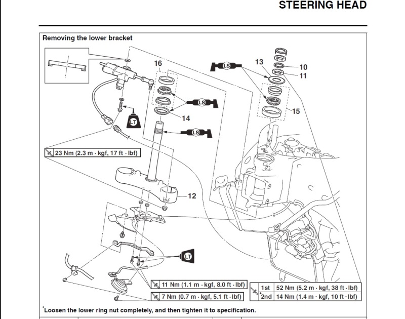
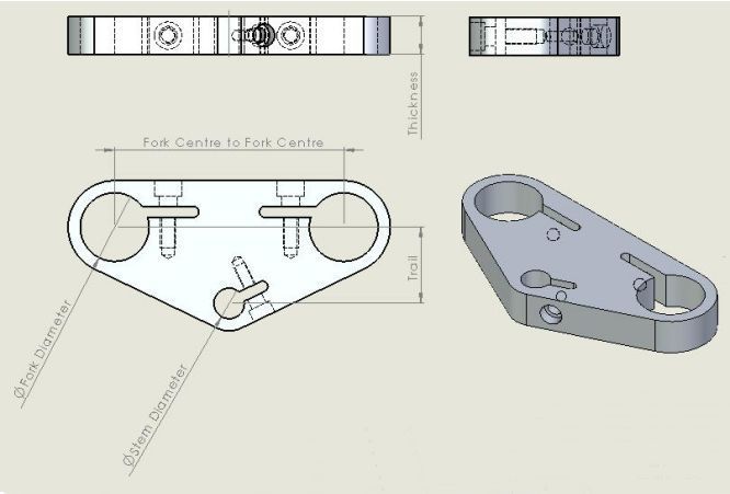
Usually in some designs that contain a hole on the part, that another shaft is supposed to pass, I see that the hole has a bolt near outside its perimeter that tightens the circle to lower radius. in cases it happens that if the hole part is cicular, it's made from two semi circles and is bolted together. what is the reason for this ?

4519814_orig_yoxfkq.jpg
 
Replies continue below

Recommended for you

Don't think of the cylindrical bit as a "shaft" - this implies it's meant to be free to move through the block.

Think of the two elements as forming part of a solid structure. The arrangement you describe is intended to clamp the two parts together, while making it possible to loosen the bolts occasionally if you need to adjust the geometry.

You need to be able to adjust the height of the saddle on a bicycle - but once you've got it to the height you want, you really need it to stay there.

A.
 
SFTmech-

The part you show is similar to a motorcycle triple clamp, which is used to attach the front forks to the steering stem. With this arrangement the fork tubes are held in place entirely by clamped friction created by torquing the clamp bolts. To get the best result from this arrangement, there must be a very close tolerance sliding fit between the triple clamp bore and the mating fork tube prior to clamping. The reason for using this single piece triple clamp design is that it provides a lighter and stiffer structure. However, one important assembly consideration with this design is that the fork tubes (and steering stem) must have one free end small enough to pass thru the triple clamp bore. When attaching other components (like curved handle bars) to a triple clamp, it may not be possible to install the part thru a fixed bore. In this case a two-piece clamp arrangement is required. Below is a picture that shows a triple clamp that uses both single and two piece clamping arrangements.

URL]
 
Why are you asking, is it something you currently use, if it is you would know the answer, or do you like posing riddles?
Added to answer your question, why - for tightening.
It is a capital mistake to theorise before one has data. Insensibly one begins to twist facts to suit theories, instead of theories to suit facts. (Sherlock Holmes - A Scandal in Bohemia.)
 
The distance noted as "trail" on the depiction does not match up with what I've always considered to be trail in a motorcycle/bicycle steering arrangement.

Edited to add: I guess the forks could be vertical, though, for whatever reason.
 
To answer your original question, a one-piece shaft collar can only be installed by slipping it over the end of the shaft. This is not always possible. A two-piece collar can be assembled directly at the point of use without having to go over the end of the shaft.

And by the way - I don't know what your application is for the part you showed above by I would not do it that way. Look at the internal stresses and strains that happen as the bolts are tightened. If your intent is that all three bore shall remain parallel, I don't think that will happen. You should redesign it so that the tightening bolt for each hole can be tightened without affecting the others.
 
Guys, thank you for the answers, my intention for asking was that to ask about a common technique as I indicated in machine construction. I thought it might have other intentions in different applications other than tightening in a certain point. Though I think the subject is well discussed by now.

Thank you very much
 
Bolts used as shown are called 'pinch bolts' for obvious reasons.

The particular geometries shown would not work very well because the flying portion is too stiff. A few minutes with a bandsaw would improve the part from that perspective.


Mike Halloran
Pembroke Pines, FL, USA
 
I'd agree with Mike that the design shown likely wouldn't function very well.

Real triple trees usually have the clamps designed such that the section of the part subject to bending load as the bolt tightens is small, so that you can get high clamp loads even with relatively small bolts.

Such as:
URL]


The dimension labeled 'trail' in that drawing is also not typically referred to as trail. 'Offset' would be a closer, but still slightly confusing, nomenclature- because total offset can be different than steering-axis-to-fork-tube distance depending on where the axle is mounted relative to the centerline of the fork tubes.
 
Yep.

The stem nut looks pretty serious because it's so big, but it actually doesn't do all that much- just keeps the upper bearing where it's supposed to be.
 
"just keeps the upper bearing where it's supposed to be."

Under the triple clamp I'd expect to find a nut (with spanner notches on the OD) that is adjusted to set the opposed tapered roller bearing clearances. Then the big nut clamps the triple clamp against the setting nut, hopefully without disturbing the bearing adjustment too much.


The Adjusting nut is item 86 here -
 
The Yamahas use two castellated ring nuts with a rubber washer in between to set lower bearing preload. The inital preload is pretty low- the torque spec for the lower ring nut is 38 ft-lb.

The spec for the big nut on the end of the stem is 80 ft-lb or so, but most guys just hand tighten them plus 1/4 turn or so. When you have the steering head apart a lot (i.e. if you're racing and replacing parts often) it's much quicker not to torque that nut to spec. There's almost no load on it so it's pretty common to do it this way.

Here's the R1 parts diagram for the lower triple tree clamp- you can see the two ring nuts and the tab washer that prevents loss of preload (or attempts to...)
Untitled_lvzhbx.jpg
 
Hi jgKRI.

Are those really caged ball bearings, not taper roller bearings?

"The inital preload is pretty low- the torque spec for the lower ring nut is 38 ft-lb."
I think 38 ft-lbs is an initial seating torque, to be loosened, then The final, operating torque is back down to 10 ft-lbs according to that diagram. Even zero rpm rolling element bearings don't think much of big preloads .

Is the stem a cylindrical diameter inside the clamp? Does the upper clamp slip off stem at disassembly? I think that the big nut is torqued to reduce/prevent micromotions of the triple clamp on the stem or vice versa. In time using reduced torque may result in fretting and wear of several surfaces there.
 
Perhaps, but I've not seen one. In every case I've seen, the upper triple clamp is a slip-fit over the steering stem, and the top nut clamps the upper triple clamp against the top of the preload adjustment nuts.

Most late model bikes have gone back to ball bearings; evidently they have less friction than tapered roller bearings.
 
An example of where the pinch bolt is positioned to allow it to perform a back-up retention function in the event loss of clamping force occurs, is the arrangement commonly used on motorcycle gear shift and kick start levers. The lever is attached to the shaft with a spline that provides positive transfer of torque. The internal spline of the lever is split and uses a pinch bolt to clamp it tightly around the mating shaft spline. The pinch bolt axis is offset radially from the spline axis so that the body of the bolt engages an annular groove in the middle of the shaft spline face width. This keeps the lever from sliding off the shaft if clamping force is lost.

pinch_bolt_zqvtps.png
 
Status
Not open for further replies.
Back
Top