Eng-Tips is the largest engineering community on the Internet

Intelligent Work Forums for Engineering Professionals

  • Congratulations waross on being selected by the Eng-Tips community for having the most helpful posts in the forums last week. Way to Go!

What is the secondary voltage when connecting 480V to each one of the primary taps ?

Status
Not open for further replies.

bdn2004

Electrical
Jan 27, 2007
792
US
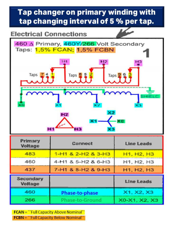
Attached is a cut sheet of the electrical connections for a SOLA isolation transformer.
What is the output voltage if we were to connect our 480V supply to each one of the different taps?
What is the formula?

For example….
Connect the 480V to the 483V tap – what is the calculated value?
What about when we connect our 480V the 460V tap?
What about when we connect 480V to the 437V tap?

What if our input voltage changes to say 490V?
 
 https://files.engineering.com/getfile.aspx?folder=544b1517-a2d3-4473-9409-6c18b8bb1ef7&file=Isolation_Transformer.pdf
Replies continue below

Recommended for you

Not much of a formula. It is a winding ratio change, +5%, -5%.
Tap ... Input ... output ... ratio
1 .... 483 ...... 460 .... 0.95
4 .... 460 ...... 460 .... 1.00
7 .... 437 ...... 460 .... 1.05

Tap ... Input ... output ... ratio
1 .... 490 ...... ??? .... 0.95 465.5
4 .... 490 ...... 490 .... 1.00
7 .... 490 ...... ??? .... 1.05 514.5

I'll let you fill in the two blanks.

(edit to add) I'm thinking you already knew that. Was there something else you are seeing?

worm

Harmless flakes working together can unleash an avalanche of destruction
 
Ratio H/L: tap 1-2-3 :1.05 (105%)
tap 4-5-6 :1 (100%)
tap 7-8-9 :0.95 (95%)

using the taps, and kwnowing your primary voltage, use the taps closer to your primary voltage to get the secondary one.
So, if you happen to have 483 V at primary, using taps 1-2-3 gives you 480 V at secondary.

Using 490 V as primary voltage results in:

connected on 1-2-3 = 467 V the closest to 460 V (490/1.05)
connected on 4-5-6 = 490 V (490/1)
connected on 7-8-9 = 516 V (490/0.95)

showing why you should use taps 1-2-3.
 
Output (X1,X2,X3) with 480V supply to H1,H2,H3:

483 tap: 480 x 460/483 = 457.1​
460 tap: 480 x 460/460 = 480​
437 tap: 480 x 460/437 = 505.3​
 
Your transformer will not maintain the ratios while underload. There will be a voltage drop across the impedances of the transformer. Just FYI if you are trying to tap to a specific voltage.

------------------------------------------------------------------------------------------
If you can't explain it to a six year old, you don't understand it yourself.
 
No not trying to tap to a specific voltage. But I am wondering one thing...

As a strategy to reduce the available short circuit energy at a panelboard or an industrial control panel...could you set to the LOWER tap to increase voltage on the secondary side and thereby decrease the available short circuit current?

We've seen cases where industrial control panels are rated for like 18kA and the available short circuit is like 19kA and the fixes are sometimes expensive and time consuming.

On a 480V system - what is the maximum allowable voltage?
 
It might be better to tell whoever provides industrial control panels to rate the panels to a certain level above 19ka.

I believe a lot of components in panels can be rated to 30ka, 60ka, 100ka. Then your not killing yourself to make these changes when the panels are installed.

This is going back to arc flash/SCCR as it relates available fault current I am assuming?

 
Yes it is about the SCCR rating of the industrial control panel. I know it’s better to have the panels built with a higher rating. And it’s known after analyzing the panels that sometimes they can be rated higher.

Unfortunately we have no control over the panel maker. And to analyze the panel someone has to pay for that too. That takes quite a bit of time to do on a large panel.

We run the software and report the numbers. And then invariably are asked what can we do to correct the issue?


Below is an edited color version of the connection diagram. I hope the color help to visualize the effect of the taps connection above and below the nominal voltage.
Tap_Changers_Transf_kt4lg7.jpg
 
Hook it up 460:460. The impedance of the transformer is going to significantly reduce the fault current compared to it not being there. Depending on how it's wound it is possible that going for the lower ratio also decreases the impedance and raises the fault current.
 
This isolation transformer did lower the fault current to an acceptable level. This was a fix. And was just one of many.

My question about raising the voltage on the secondary side is in relation to the main upstream 12.47kV - 480v transformer that supplies the 480v to this system. By raising the voltage slightly on the secondary side, the short circuit current goes down slightly making all these isolation transformers unnecessary.

I’m wondering if this is a valid strategy.

 
Same thing about actual transformer winding configuration. Lowering the ratio may lower the fault current or it may raise the fault current. Unless you have an impedance test report for every tap you won’t know. But if you’re that close you should consider yourself well over the line. Unless you’re starting with an infinite bus you’re dealing with modeling uncertainty. Do all of the modeling issues make your numbers more conservative? If not you should be very leery of solutions that work on a few percent change in something.

I’ve been there and done that and the more I learn the more I wish I hadn’t. No known issues of things going bad, just an ever increasing awareness of just how rough a calculation a fault value really is. Call it a ball park guess and allow a wide tolerance.
 
Status
Not open for further replies.

Part and Inventory Search

Sponsor

Back
Top