Continue to Site

Eng-Tips is the largest engineering community on the Internet

Intelligent Work Forums for Engineering Professionals

  • Congratulations MintJulep on being selected by the Eng-Tips community for having the most helpful posts in the forums last week. Way to Go!

What is this LV earthing system called? 2

Status
Not open for further replies.

veritas

Electrical
Oct 30, 2003
467
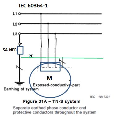
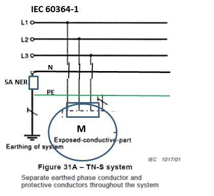
I am curious as to what the LV system in the attached drawing would be called. I am aware of TN-C and TN-C-S and TT systems. But what if the supply trfr neutral is high impedance earthed via a 5A neutral earthing resistor as shown in the diagram?

Thanks.
 
 https://files.engineering.com/getfile.aspx?folder=88e9a8c5-36be-4372-a67e-30a997631676&file=What_is_this_LV_earthing_system_called.pdf
Replies continue below

Recommended for you

In my opinion, it is TN_S.
IEC_60364_TN_S_wobffk.jpg
 
I know it cannot be TN as
1) the neutral is not solidly earthed and
2) there is no neutral at all

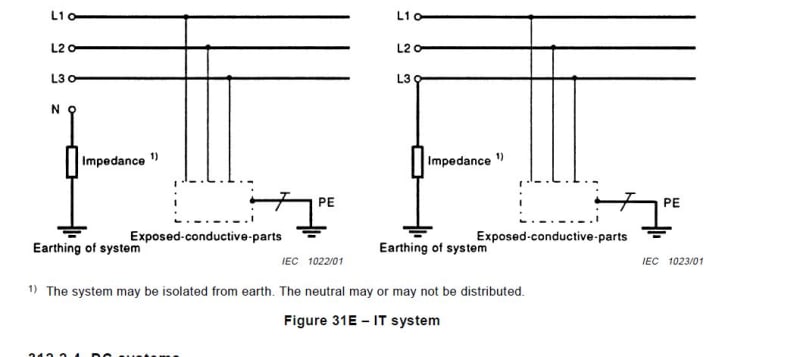
But an IT system as far as I know (could be deadwrong) means neutral is totally insulated from earth or is earthed through a high impedance like we have here. However, T means that the exposed conductive parts at the installation end are tied to ground at the installation point of intake. However, here we have a protective earth running all the way back to the source so earths within the installation are not solely connected to ground but connected to the earthing point of the NER at the source. So I'm still puzzled as to what this is. An I-S system?

 
How is it IT if there is PE running from the load all the way back to the source? Does the T not mean locally earthed only?
 
The PE is not running back to the source.
The PE is running back to the grounded end of the NER.
Not the same.
Your diagram shows the path of fault currents.
It is useful to determine the voltage rise on the surface of the motor in the event of a ground fault in the motor.
It is useful for comparison with a solidly earthed system.
With a 5 Amp NER the voltage rise on the surface of the motor will be negligible.
With a solidly grounded system the voltage rise on the surface of the motor may rise to over 1/2 of the phase to neutral voltage in the event of an internal ground fault in the motor.

Bill
--------------------
"Why not the best?"
Jimmy Carter
 
waross,

Yes, grounded end of the NER is at the source end is what I meant. I get it with regards to the difference in voltage rise (touch voltage) between the solidly earthed case and the NER case.

My question is in relation to the correct designation for the kind of LV earthing system in my diagram. So far I have not yet seen a designation that is satisfactorily explained.
 
I just want to say something. No matter how the neutral is grounded, if it all, all the metal cases (loads) must be tied together. Even if the supply is giving power to different structures all of them must be tied together.
 
I would consider the ungrounded end of the NER to be the source.
The ground is the ground is the ground.
Best practice is to tie the equipment grounds and the grounded end of the NER together.

Bill
--------------------
"Why not the best?"
Jimmy Carter
 
No matter how the neutral is grounded, if it all, all the metal cases (loads) must be tied together. Even if the supply is giving power to different structures all of them must be tied together.

Best practice is to tie the equipment grounds and the grounded end of the NER together.

I certainly concur with both statements above provided it is practically possible. In a pure TT system there is no PE from the load to source. However, all loads within an installation should be bonded together, agreed.

I am still yearning for someone to enlighten me as to the answer to my original question. [ponder]
 
Definitely not IT! I= isole (insulated in French), but you have an "earthed" line 2 of the supply lines there! My only question is why the NER is ahead of the line supplied to the loads?
 
But in a pure TT system you have an RCD which clears the first fault.


In a IT system without structures being bonded together a fault could develop in one structure on phase A and a fault on another structure on phase B. Both faults would remain energized, and the 230 volt potential between buildings could start a fire.


BTW,where IT is used, typically the neutral is not distributed and all loads are connected line-line.
 
Yes- typically not distributed.


Tie the structures together, or add an RCD so the earthing system does not become energized one two standing ground faults.


I am well aware in place like Norway that they never tied the buildings together with a PE, however that had lead to many fires.
 
Status
Not open for further replies.

Part and Inventory Search

Sponsor