MiniG1
Mechanical
- Feb 21, 2011
- 2
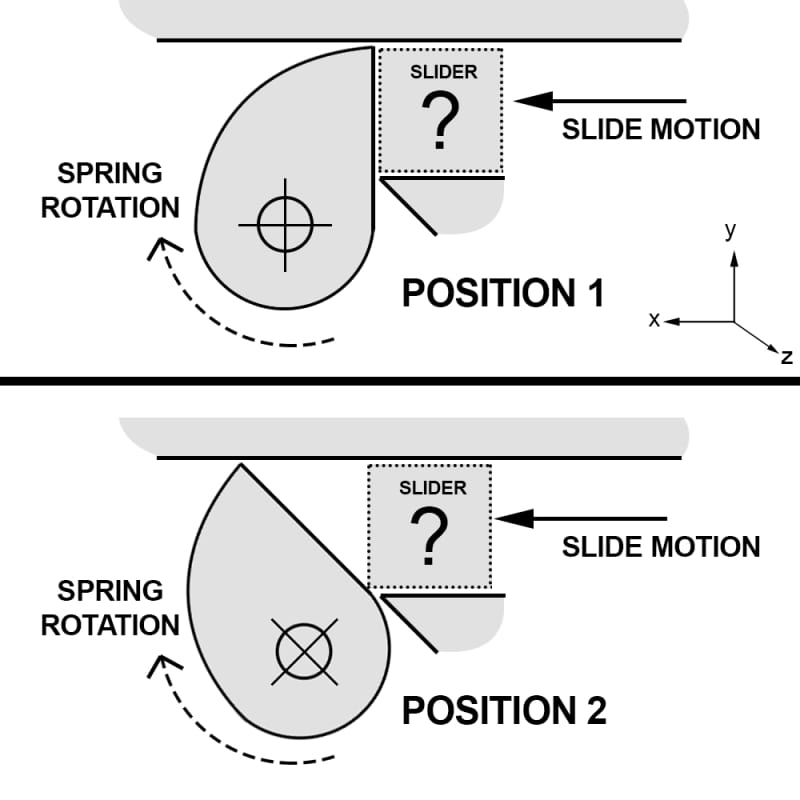
I am looking for mechanism ideas, examples or feedback on how I should convert the sliding motion of a part to the 45 degrees rotation of another one (see picture).
I have a "slider" of an undetermined shape that can move freely along the x+ axis. The slider is to be pushed by a human finger. I have another "pivot" part that can rotate around the z axis. A spring forces this part to go back to POSITION 1 at rest. I want to be able to force a rotation of this part by 45 degrees (POSITION 2) when a x+ motion is applied on the slider. When the slider is released, I want to the pivot part and the slider to go back to POSITION 1.
I am open to change the shape and/or mechanism for both parts, as long as what is described above is respected. The slider would be stuck in a rail / cannot move along the y nor the z axis. The diameter of the pivot part is ~6mm and the sliding motion would only be of a few mms (~2mm). The parts would be made of zinc alloy.
Thanks![[bigsmile] [bigsmile] [bigsmile]](/data/assets/smilies/bigsmile.gif)

I have a "slider" of an undetermined shape that can move freely along the x+ axis. The slider is to be pushed by a human finger. I have another "pivot" part that can rotate around the z axis. A spring forces this part to go back to POSITION 1 at rest. I want to be able to force a rotation of this part by 45 degrees (POSITION 2) when a x+ motion is applied on the slider. When the slider is released, I want to the pivot part and the slider to go back to POSITION 1.
I am open to change the shape and/or mechanism for both parts, as long as what is described above is respected. The slider would be stuck in a rail / cannot move along the y nor the z axis. The diameter of the pivot part is ~6mm and the sliding motion would only be of a few mms (~2mm). The parts would be made of zinc alloy.
Thanks
![[bigsmile] [bigsmile] [bigsmile]](/data/assets/smilies/bigsmile.gif)


![[wink] [wink] [wink]](/data/assets/smilies/wink.gif)
