Continue to Site

Eng-Tips is the largest engineering community on the Internet

Intelligent Work Forums for Engineering Professionals

  • Congratulations KootK on being selected by the Eng-Tips community for having the most helpful posts in the forums last week. Way to Go!

What should be section thickness when there is nodal equivalence between shell and Solid parts ?

Status
Not open for further replies.

VaidehiChennubhotla

Mechanical
Jun 14, 2018
32
I have a shell structure and solid structure with merged nodes (Nodal equivalence) in Abaqus. The thickness of the shell structure is 1.5 mm . What should be the section thickness that I should assign in *section ?Generally we select the mid-surface for assigning the section thickness. I dont want the shell structure to penetrate into the solid structure as I have merged the nodes.
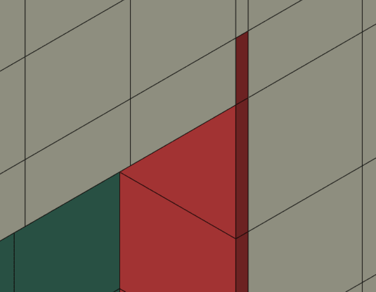
no_wiyijf.png

Red is the shell
White is Solid
Green is solid
 
Replies continue below

Recommended for you

How did you merge the nodes ? In Abaqus there’s no such option as nodal equivalence so I guess that you used HyperMesh for meshing.

Anyway, you can use shell offset option in Abaqus if you want to offset shell’s reference surface from midsurface. However, you should make a space in solid parts for shell with given thickness to avoid interference.
 
Hi FEA way,

I used merge instances to merge the shell and solid part into one single part. Then in the part module, I merged the nodes at the interface of the shell and the solid. I don't have access to Hypermesh but I think Hypermesh nodal equivalence helps to have nodal equivalence between shell(mid surface) and solid, without compromising on the thickness of the shell structure.Please correct me if I am wrong. I am getting the following error also.

***ERROR: THE NODAL THICKNESS PARAMETER WAS SPECIFIED FOR ELEMENT 301 BUT THE
*NODAL THICKNESS OPTION WAS NOT USED
***NOTE: DUE TO AN INPUT ERROR THE ANALYSIS PRE-PROCESSOR HAS BEEN UNABLE TO
INTERPRET SOME DATA. SUBSEQUENT ERRORS MAY BE CAUSED BY THIS OMISSION
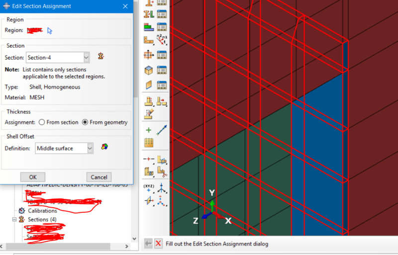
section_from_geometry_a79mt2.png


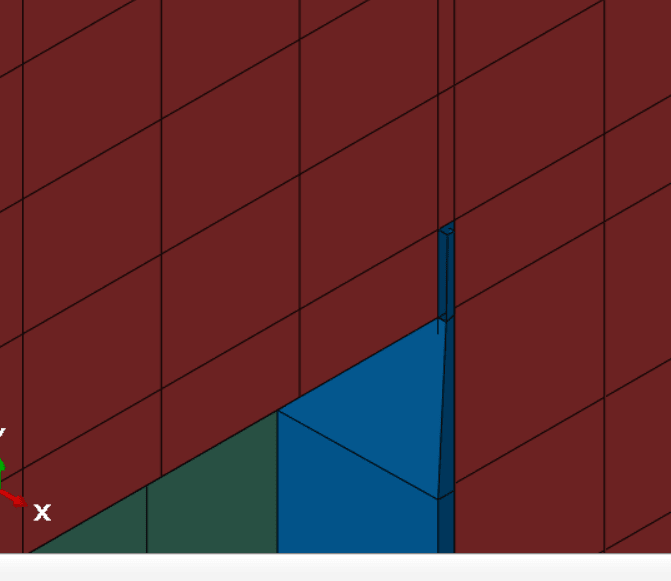
I dont want to change the geometry of the solid part. Taking the shell offset from midsurface is adding thickess on the inside as shown below.
shell_offset_from_mid_surface_s5kqi8.png
 
You could also use tie constraint instead of merging nodes. It would be easier this way.

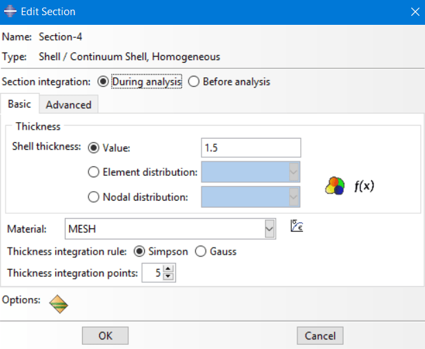
The error that you get refers to variable shell thickness defined on the nodal basis. How did you set this feature ?
 
Hi FEA way,

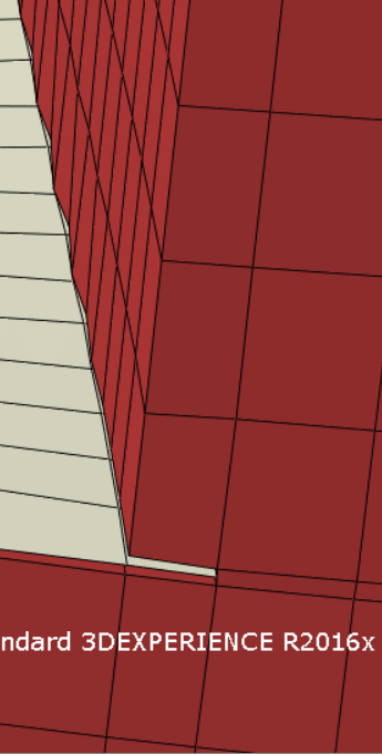
Using tie the nodes which are tied are like attached and rest of the element is becoming wavy. I didnt use variable shell thickness based on nodal distribution.
tie_constraint_vqu8fh.png

not_variable_shell_thickness_mo55ex.png
 
That’s most likely because of insufficient adjustment tolerance. In tie constraint settings switch from "Use computed default" to "Specify distance" and enter the approximate distance between the nodes that should be connected (increased a bit just in case).

Variable shell thickness is a functionality that allows you to define shells with spatially varying thickness. It can be defined in shell section editor (Shell thickness —> Element distribution or Nodal distribution). I assumed that you used this feature because the error that you had was referring to it.

I noticed that your shell section assignment uses thickness from geometry. You should switch to "From section" if you want to specify thickness in the section editor.
 
Hi FEA way,

Shell section assignment using thickness From section option and mid surface is having convergence issues. I have not used variable shell thickness.
Contact pairs are giving convergence errors so I used general contact.
 
Status
Not open for further replies.

Part and Inventory Search

Sponsor