Continue to Site

Eng-Tips is the largest engineering community on the Internet

Intelligent Work Forums for Engineering Professionals

  • Congratulations MintJulep on being selected by the Eng-Tips community for having the most helpful posts in the forums last week. Way to Go!

What size primary injection set do I need? 1

Status
Not open for further replies.

veritas

Electrical
Oct 30, 2003
467
I need to do the primary injection diff protection stability testing of a 5MVA 33/11kV 7.15% trfr first of all. Afterwards 4.8MVA 11kV generator needs to be primary injected.

33kV CT's are 150/1 and 11kV CT's are 300/1.

I need to have at least 20A at 33kV to operate the diff or 60A @11kV.

I presume one needs to size the injection set required by current and VA output? The practicality of the situation necessitates that the injection set be connected at the 11kV end. So it needs to be able to deliver > 60A but what should it's VA rating be?

Thanks.
 
Replies continue below

Recommended for you

Why not use the generator itself? Hint-manually control the excitation for a low voltage. Apply grounds on the HV side of transformer.
Another hint - if the CT's are inside the transformer, there is no practical way to use a separate test set - the transformer impedance will be too high.
 
Good suggestion above, that's the way to do it if the set is runnable. You can steer current where you need it using the HV earths. You won't need much field voltage to raise a fair bit of current in the windings so make sure you have a PSU with a fine adjustment.

Failing that, get a rental genset and put a variable DC lab supply in lieu of the AVR field connections. With a rental set you might need to disable some or all of the protection and/or disable the trip coil to the breaker to make it useable. Which is OK as long as the rental companay don't know about it. ;-)
 
Another hint - if the CT's are inside the transformer, there is no practical way to use a separate test set - the transformer impedance will be too high.

Not sure I understand what the trfr impedance has to do with the CT location? HV and LV CT's are both outside the trfr. also, generator is not ready.

Customer wants to use the Omicron CPC100 (or the CMC356) which can deliver up to 800A and up to 5kVA. Not sure how to determine if the CPC100 has sufficient grunt.
 
No conventional primary set has sufficient drive voltage to drive useful current through a transformer's windings. Do the maths: you'll need nearly 800V to circulate rated current in that transformer if you put a dead short on the HV terminals and inject on the LV terminals. Even a big primary set can only muster about 10V or so open circuit, and that voltage would only circulate about three amps or so in the winding.

A 400V rental generator will circulate about 50% of rated current in the windings, but you'll be looking at a 200kVA / 250kVA set to deliver that amount of current. If you don't need that kind of current then do as I said earlier and use a lab PSU to directly control the generator field, effectively making it into a very high power Variac from which you can dial in whatever current you need.


Edit:
The CPC100 can manage 6V open circuit on the 800A output, or 2.5V with the 2000A loading unit. It's a reasonable lightweight set, but it's no use for the test you're trying to do - it hasn't got the drive voltage to push more than a couple of amps through the transformer.
 
Hi Scotty

I've done the maths as well. All I want is enough current to operate the diff for an inzone fault. I need 60A @11kV. Trfr impedance is 1.73ohms @11kV. So the test-set output voltage will need to be 60A * 1.73 = 104V (L-N) or 180V (L-L). This gives a required power of sqrt(3)*180*60 = 18.7kVA. CPC100 can only manage 5VA so as you say, no good.
 
Scotty,

Just a question regarding your calcs:

Rated LV current is 262.4A @11kV. ZBASE = V^2/MVA = 121/5 = 24.2ohms. Thus ZT = 24.2 * 0.0715 = 1.73ohms @11kV

Now 50% of rated current is 130A, which gives a voltage of 130*1.73 = 225V (L-N) or 390V (L-L). This gives a power requirement of 1.73 * 130A * 390V = 87.8kVA which is way less than your 200kVA/250kVA. Did I make a blunder somewhere?


No, it's my error [blush] - my calcs were slightly less precise than yours (pen & paper) but I incorrectly used 265A / 400V to size the set instead of half that current at 400V. Thanks for cross-checking my numbers - at least you can see why the primary set is useless in this application. :)

200kVA sets aren't common in our local rental fleet but 250's are, hence the comment on generator size.
 
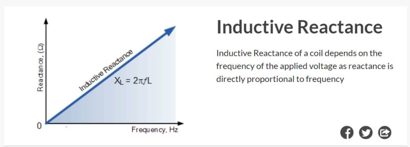
One thing you can do with the CPC100 is reduce the injection frequency and the impedance of the circuit. It goes down to 15hZ, I believe. If you can reduce the injection frequency to, say 40Hz on a 50Hz basis, your relays may still read this.
 
Phew! Thanks for that. Though I had made a blunder somewhere. The reduced frequency is an interesting idea but yes, I'm wondering if the relay (SEL-700G) filtering will kick in and also, how much additional current will it really allow? I.e what is the decrease in trfr %Z in going from 50 to 40Hz? Did not do the maths yet.

I did mention to the client to use the generator itself to do the primary balance injection tests and he has really warmed up to the idea as he is keen to get the thing spinning and do some checks his side as well. So all looks set for using the gen itself.

Thanks for all the posts. As usual, I've learned a great deal again!
 
A SEL 700G has the following frequency specifications:

Frequency and Phase Rotation
System Frequency: 50, 60 Hz
Phase Rotation: ABC, ACB
Frequency Tracking: 15–70 Hz
reactance_pwdh5b.jpg


Years ago I was asked to commission the protection on an 8 unit GE LM6000 peaker plant. Everything was "rush rush", are you done yet. The excitation specialist from Brush was there at the same time. After a short discussion, we agreed to perform Primary Injection, as he wanted to check a few things on his end. The units had an Aux feed for starting so some minor switching and we could run the units up without much fuss. Two simple test connections were made. First we placed 3 phase shorts/grounds on the HV side of the GSU. With this connection the Brush guy manually ramped the generator voltage up until we had sufficient through (restraint) current. The checks into the relay went very quickly. For the second test, the HV shorts were removed (unit off) and a single short was placed, phase to ground, on the LV bus (gen) side. Again the generator voltage was slowly ramped up. In this case we were proving the 59N VT connections. After the first unit procedure was in place, we were off and running and were able to check the entire plant (8 units) in one long day.

Two years I commissioned a large breaker and a half switchyard (12 breakers). We used a CPC-100 primary voltage & current & a CMC for a voltage reference. I used the CMC to feed the secondary side of the CCVT circuit for a voltage reference in the relay house as well as a sync source for the CPC-100. Each of the 12 breakers utilized ~15 CT's. We checked every CT circuit and also checked every CCVT (primary voltage from CPC) circuit in two days, including the "dog and pony show" demonstration with the client in two days. A two man crew, with one at the relays and one out at each breaker or bus diff summation box, shorting CT contributions made the process go very smoothly. Using the SEL relays and logging the meter and meter dif and trigger commands made the documentation quite easy. We utilized make before break switching of the breakers to steer the current down each diameter. Initially I was concerned about circuit impedance on the CPC. I utilized the sequencer test card and the looping function. I found a sweet spot of about 200A and made a duty cycle of 1/3 on off time. Normally the day of energizing is one that ties the stomach in knots. In our case, it was a relaxing day. :)
 
Status
Not open for further replies.

Part and Inventory Search

Sponsor