Attached is tie rod dwg. I am trying to do a FEA on the tie rod but results was not what I wanted.
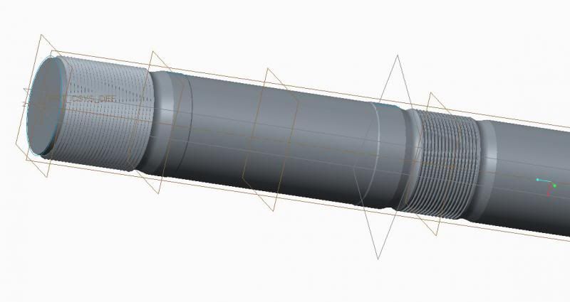
Anyway, I will start by explaning this tie rod. There are four tie rod that hold two platen in place. The picture shows half of a tie rod cuz I used a symmetric constraint on it.
It has thread diameter of 9 1/2". So just using basic calculation with 825000 pre load on the tie rod. The stress should be around 12500 psi. But using FEA software (creo), the lowest stress I get by changing the constraint is 52000 psi. that's way too much for the material. I am wondering if I constraint it correctly.
Here is how i constraint it, I created a region where the nuts thread contact with the tie rod thread, I put the 825000 lb on this region on every thread.
Then on the opposite side of the thread (across from the above region, ie the slope part of the thread) I put a displacement constraint of tiying doen XYZ translation.
I am not sure if that's enough or can someone explain to me how to constraint a thread.
Thanks
Howard