Continue to Site

Eng-Tips is the largest engineering community on the Internet

Intelligent Work Forums for Engineering Professionals

  • Congratulations SDETERS on being selected by the Eng-Tips community for having the most helpful posts in the forums last week. Way to Go!

Which constraints should I set to simulate stiffened panel under pure shear?

Status
Not open for further replies.

Eugene Pavlov

Mechanical
Nov 10, 2020
4
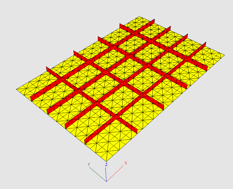
I have a stiffened panel that looks like this:
stiffened_panel_bx6nvj.png


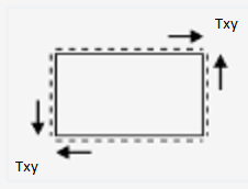
This panel is under shear:
stiffened_panel_txy_rfi6xi.png


All sides of the panel are pinned. Txy - is distributed shear load.
Which constraints should I set to simulate stiffened panel under pure shear?

[pre]
As for me I did this (but don't know is it good approach):
Constraints:
Tx Ty Tz Rx Ry Rz
Left: - - x - - x
Right: - - x - - x
Top: - - x - - x
Bottom: - - x - - x
A: x x - - - -
D: - x - - - -

Where: Tx, Ty, Tz - translational degrees of freedom
Rx, Ry, Rz - rotational degrees of freedom
'-' denotes free degree of freedom
'x' denotes fixed degree of freedom
A - left bottom node // B ---- C
D - right bottom node // | |
// A ---- D

Then I set distributed load on each side in appropriate direction.
[/pre]
So which kind of constraints would you advice?
 
Replies continue below

Recommended for you

Generally those boundary conditions seem correct apart from unnecessary constraint Rz=0 for all edges.

If you are not sure about BCs, run a simple test analysis of a rectangular plate (without stiffeners) subjected to in-plane shear. Its results should show you whether the constraints are correct or not.
 
ok, you've constrained the plate for shear, now how are you going to load it ? Replace constraints on a long side and a short side with UDL. Well a "proper" UDL ... 1/2 the QUAD load at each node (so that the extreme end nodes see only 1/2 the typical node load, yes?)

another day in paradise, or is paradise one day closer ?
 
Some FEA programs offer special load called shell edge load and one of its types is shear. But of course it depends which software is used.
 
another thing ... are the stiffeners 1D elements (rods) or 2D elements (cap and web) ? what constraint for the non-shear_web node ? I'd suggest axial load.

another day in paradise, or is paradise one day closer ?
 
EP - do you want the edges to remain straight? Your bc’s will not enforce that.

Start with an unstiffened plate model and work out loads and bc’s to get a state of pure shear stress. Then move to the stiffened panel.

And remesh with quad elements. If you are using 4 noded tet elements the results will be rubbish (at best).
 
You can have a look here under the INDIVIDUAL DOCUMENTS section. For the Basic Manual, Page 7 discusses the boundary conditions and some specifics about it. The Validation Cases PDF shows that this approach is accurate for in-plane loading (Nxy loading).


Brian
 
yeah, but "straight" edges is like "fixed constraint" ... a theoretical "construct" rather than a true reality.

I agree with the approach of starting with a simpler model and loading, and get that right (or "right") and adding complication.
One thing to think about is "what's beyond the model?" is it a rigid body or a theoretically infinite shear panel ? Possibly model as a cylinder if infinite ? Possibly model as "super-element" and combine 9 (16?, 25 ??) pieces together to see what happens.

For edges, maybe add a beam with very low area but very high I

yeah, avoid TET4s like they were some "red-haired orphan". But meshing this with TETs would take a lot of elements ! (but so what if it takes 5 minutes to run ...)

another day in paradise, or is paradise one day closer ?
 
Status
Not open for further replies.

Part and Inventory Search

Sponsor