Continue to Site

Eng-Tips is the largest engineering community on the Internet

Intelligent Work Forums for Engineering Professionals

  • Congratulations IDS on being selected by the Eng-Tips community for having the most helpful posts in the forums last week. Way to Go!

Why are neutral axis different when checking ultimate moment and cracked inertia?

canadiancastor

Structural
Apr 13, 2014
37
I'm having a look at some formula I use all the time and wondering why two things I'm calling the neutral axis appear to be different things. Or maybe there's a simplification that we're doing that I don't quite understand.
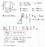
In the first example, we are looking at strain, then stress, then finding a balance between compresion and tension forces.
In the second example, we are looking at simply the areas * lever arm of compression vs tension and balancing those. This is quite different than number 1, specialy if you have a triangular distribution of strain in the concrete (low stress).
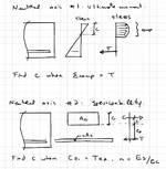
1744162489870.png

The actual question behind this is that if serviceabillity is always in the elastic range, shouldn't we assume that the concrete has a triangular strain and stress distribution? If so, would we not need to take the lever arm about the center of gravity of the triangle (2/3 * c) and the area of the triangle as 1/2 of the rectangular area? This would be akin to what is done in the ultimate moment determination of the neutral axis.
 
Solution
Found out where I was mistaken:
  1. The difference between the first and second example is how where we are the on the moment-curvature curve. The first example is way further along, where the concrete has become non-linear, so the neutral axis has somewhat receded from it's elastic value.
  2. As long as we stay in the elastic domain, the neutral axis is theoretically stable
  3. The place where I was confused was why the equation given below in many textbooks this not seem to take into account the triangular distribution of stress in the concrete
1744208078367.png
Doing a hand calc shows that the equation DOES take into account the triangular distribution (by using an average strain at the center of each area), it just doesn't look that...
Replies continue below

Recommended for you

Normally the serviceability condition (in my world anyway) would be done to check whether the concrete section cracks under daily loading
The goal of this is to use the full concrete section properties for stiffness
In this case, there is a triangular stress-strain distribution above and below the NA which is located at the beam centreline (assuming a rectangular beam)
I neglect the area of the steel in this calculation though you could transform it and include it if you wanted to be precise
You can then calculate your uncracked beam properties using standard Ix and Zx formula for rectangles

This assumes that your concrete is reliably not cracked already of course - otherwise you are in an effective moment of inertia situation which is probably 5-10% of the gross section for non-seismic loading

You also need to be careful that the linear stress-strain distribution in concrete is not always true
As strain increases, the stress response will become non-linear
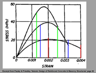
I have a spreadsheet I made for checking the moment capacity of strain-limited concrete walls and I based my limiting concrete strain on some data from Paulay & Priestly - snip attached for reference

1744163235013.png
 
I'm having a look at some formula I use all the time and wondering why two things I'm calling the neutral axis appear to be different things. Or maybe there's a simplification that we're doing that I don't quite understand.
In the first example, we are looking at strain, then stress, then finding a balance between compresion and tension forces.
In the second example, we are looking at simply the areas * lever arm of compression vs tension and balancing those. This is quite different than number 1, specialy if you have a triangular distribution of strain in the concrete (low stress).

View attachment 7997

The actual question behind this is that if serviceabillity is always in the elastic range, shouldn't we assume that the concrete has a triangular strain and stress distribution? If so, would we not need to take the lever arm about the center of gravity of the triangle (2/3 * c) and the area of the triangle as 1/2 of the rectangular area? This would be akin to what is done in the ultimate moment determination of the neutral axis.
Neither of those calculations have anything to do with bending moments.

For a rectangular stress block with a specified stress the force in the concrete = stress x area.

For a linear-elastic stress block we don't know the stress, but it is proportional to the distance from the neutral axis. The force is therefore proportional to the integral of the width times the distance from the base, which is the first moment of area of the concrete section above the neutral axis. For the steel the force is proportional to area x distance from NA x Es/Ec, so the calculation is equalising the forces assuming elastic behaviour in the steel and concrete in compression.

Both calculations assume a fully cracked section, and ignore tension stiffening effects.
 
Don't exactly understand your question. hopefully one of these is answer.

"If so, would we not need to take the lever arm about the center of gravity of the triangle (2/3 * c) and the area of the triangle as 1/2 of the rectangular area?"

Yes. ULS calculation where concrete stress is assumed constant using rectangular stress block gives linear equation to solve. serviceability calculation like you said gives quadratic because max stress * depth to NA gives square term. You can tabulate NA depth against reinf ratio and steel:concrete modular ratio if useful for hand calcs but not really needed with computers.


"In the second example, we are looking at simply the areas * lever arm of compression vs tension and balancing those. This is quite different than number 1"

This is just from dealing with different Youngs modulus different ways. In #1 you use real parameters. In #2 you pretend steel has same modulus as concrete but you have more steel than you really do. #2 becomes a geometry problem with simpler units.


"wondering why two things I'm calling the neutral axis appear to be different things."

This is where I really don't understand what you mean so will guess. Think of asymmetric steel section with different elastic and plastic centroid locations. Those are neutral axis locations before first yield and at full plasticity. In between the NA moves as moment increases. Same with reinforced concrete which is asymmetric. NA for triangular strain distribution at low stress isn't in the same place as ULS. So I'm answering question of why NA depth changes between #1 and #2 if that's what you're asking.
 
Found out where I was mistaken:
  1. The difference between the first and second example is how where we are the on the moment-curvature curve. The first example is way further along, where the concrete has become non-linear, so the neutral axis has somewhat receded from it's elastic value.
  2. As long as we stay in the elastic domain, the neutral axis is theoretically stable
  3. The place where I was confused was why the equation given below in many textbooks this not seem to take into account the triangular distribution of stress in the concrete
1744208078367.png
Doing a hand calc shows that the equation DOES take into account the triangular distribution (by using an average strain at the center of each area), it just doesn't look that way once the terms cancel out.
1744208269256.png
 
Solution

Part and Inventory Search

Sponsor