Eng-Tips is the largest engineering community on the Internet

Intelligent Work Forums for Engineering Professionals

Why do people use VRT (Vapor Recovery Tower)? 1

Status
Not open for further replies.

aegis4048

Petroleum
Apr 23, 2024
35
0
0
US
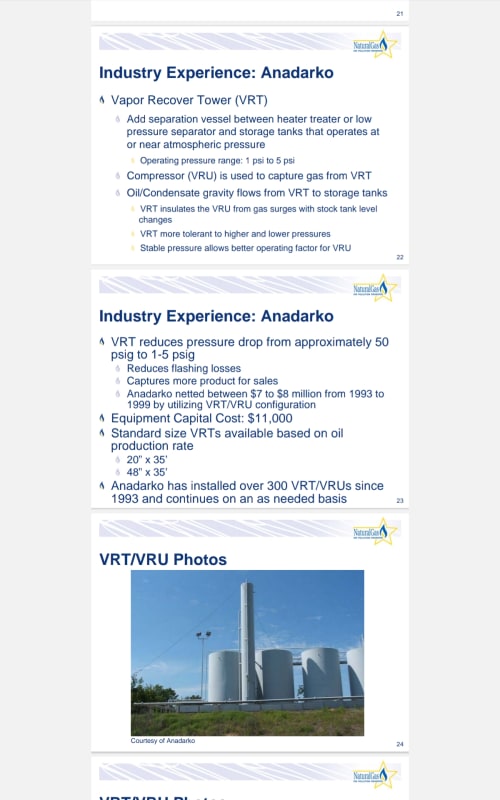
I never understood the purposes of using VRTs. The VRTs operate around 3~5 psig and gravity-feeds the separated liquid into the tank using VRT's own height. The VRTs are usually hooked up to a VRU, so if you can separate as much gas as possible from the VRT before atmospheric tanks, you can recover more of those rich vapors.

But why can't we just skip VRT, and directly hookup compressors on atmospheric tanks? To me VRT just seems like an extra middle man that's not needed because the technology allows us to directly pull vapors from tanks with compressor suction.

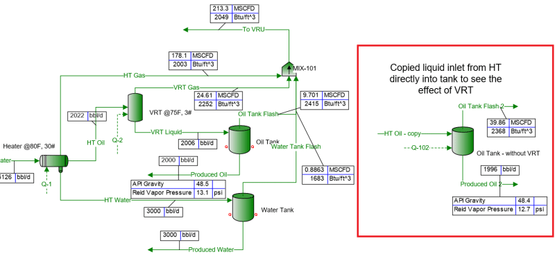
The below image is a process simulation I ran for with VRT vs. without VRT. You can see that the scenario with the VRT produces ~4 bbl more oil, but this is definitely not enough to justify the cost of installing an additional vessel.

withVRT_plhtx2.png
 
Replies continue below

Recommended for you

Maybe you mean that your particular oil does not contain enough vapors to make to economical to do it. Run your sim with API 60

--Einstein gave the same test to students every year. When asked why he would do something like that, "Because the answers had changed."
 
In high vapor fraction situations, it can take some time for equilibrium, and hence a tank.

= = = = = = = = = = = = = = = = = = = =
P.E. Metallurgy, consulting work welcomed
 
Your VRT looks to me like another name for a degassing vessel?

The key issue is the design pressure. Vessels can be quite small but designed for say 5psi.

"Tanks" on the other hand are often much bigger and have very low design pressures so can't handle volatile liquidswith large amounts of gas off.

Remember - More details = better answers
Also: If you get a response it's polite to respond to it.
 
This VRT is also called a degassing boot. Design pressure of this drum is 50-100psig, has PSV connected to LP flare header but operates at very low pressure. It can handle emergency gas blowby from the upstream separator, while the API650 tank (max design press of 2.5psig) cannot.
 
@georgeverghese

Still doesn't make sense to me. I'm assuming the emergency blowby from the upstream separator, you mean a high pressure stream that can potentially dmg the low-pressure rated tanks. But can't this be handled by simply pressure regulators to ensure the stream coming into the tanks are low pressure?

I mean, I see many facilities without VRTs these days and just pulling directly off the tanks.
 
A gas blowby scenario occurs when operational and even safety process controls fail. API guidelines require that we consider any such regulators / other control devices to have failed in an emergency - see API520 and 521. Such failures can also occur as a result of unintended misoperation or deliberate disarming of safety controls(which frequently occurs during maintenance routines). Besides, a gas blowby is usually a fast acting transient and normal control devices simply wont be able to react quickly enough to cut off the source of high pressure.
 
If you're just running the line into a low pressure separation tank, you must blow off all the high vapor pressure liquids in the stream. High API crudes may contain a lot. If you do not capture those vapors, you lose product, revenue value and pollute the atmosphere. Crude are getting lighter and gas emission limits are now more strict, hence more VRT are in use. The days of blowing it off to atmosphere are over. Move on.


--Einstein gave the same test to students every year. When asked why he would do something like that, "Because the answers had changed."
 
@1503-44
There will be no lost vapors vented & flared from the atmospheric tanks because the VRU will be running. Doesn't matter if the crude is high API or not, because all the flash & working & breathing vapors will flow into the suction of the VRU, which operates at 4~8oz, which is below a PRV and thief hatch set points.

In fact, you lose more vapor by installing a VRT. In presence of a VRT, the VRU is usually hooked up only to the gas outlet of the VRT. While the VRT operates at 3 psig to it can capture "most" of the vapors, there are still ~3 psig to flash at the atmospheric tanks. These flash gases will have no where to go other than vented & flared, because no operators are gonna install 2 VRUs: 1 for the VRT, and 1 for the tanks. The only potential problem I see is the gas blowby problem @georgeverghese mentioned.

With VRT: VRU is hooked only to the VRT operating at 3 psig. The ~3 psig worth of gas that aren't flashed from the VRT will be flashed from the atmospheric tanks. The flash gas from the tanks will have to be vented or flared, because there's no VRU hooked up to the tanks

Without VRT: VRU is hooked up directly to the tanks, and it recovers every vapor flashing from the tanks to the suction of the VRU. No flaring & no relief valve venting because all gas will be sucked into the VRU.

Please check out the attached PDF: 1 scenario with VRT vs. without VRT. It's a process sim schematic I built recently.

@georgeverghese
Sure, we have to consider those pressure regulators before the tanks failing, but that's what the VRU suction & thief hatch & relief valves on the tanks are for (plus any low-level control devices on upstream separators). In case the regulators fail, the safety devices on the tanks can handle overpressure by venting the excess gas (though as long as the VRU's running, I don't expect seeing these vent events). I don't see the cost of installing an extra VRT being justified because there's other safety alternatives, especially when I'm seeing operators that don't put VRTs these days, but instead pulling off gas directly from the tanks with VRUs.

And putting that extra high-pressure rated VRT (50~100 psig) doesn't mean you can get away from failure scenarios. The regulator before the inlet of the VRT can also fail.
 
 https://files.engineering.com/getfile.aspx?folder=1326fdf4-d672-4884-9fbe-baa0d5b2a552&file=pfd_-_for_eng-tips.pdf
Your vapor pressures are low. A high API crude is boiling at atmospheric pressure, so you can't put it in an API 650 atmospheric pressure tank.

--Einstein gave the same test to students every year. When asked why he would do something like that, "Because the answers had changed."
 
@1503-44

In the uploaded PFD, the vapor pressure is low because I operate the heater at 150F, providing sufficient heat to flash off most gases in the liquid stream. If I turn off the heater and operate at 80F, the liquid in the tank reports 20 psia, which is above 14.7 and therefore boiling as you mentioned.

Let's say that I turned off the heater, and the liquid in the tank operate at 80F today. The reported vapor pressure in this condition is 20 psia. Two points to make here:

1) TVP is a vapor pressure of a liquid in equilibrium at 100F, according to ASTM D1267 method. For now, the tank operates at 80F, and it's stable. But it will start evolving gases if temperature goes up during a hot summer day, experiencing severe flashing & working & breathing losses. THIS STILL DOESN'T MATTER, because even if the liquid in the tank is above 14.7 psia TVP, and therefore boiling, because that boiled flash gas will still be captured by the VRU. As long as the VRU is there, no venting or flaring will occur. The suction of the VRU for atmospheric tanks is always set under 10oz, so if the VRU is properly sized to handle all vapor volumes, and its running, the pressure in the tanks will maintain below the thief hatch & PRV thresholds, and flare line back pressure.

2) Installing a VRT has barely any effect on lowering the TVP, the main driver to TVP is the temperature of the heater according to my sim results.

I'm still unconvinced for the need to use VRT. Contrary to what most ppl has been thinking traditionally, VRT makes you lose more vapor because if you choose to put VRT, then a compressor will be hooked up only to the VRT, and won't be hooked up to the tanks. And the flashing & working & breathing losses from tanks that will evolve due to ~3 psig on differential from the VRT will have to be flared or vented - this is a revenue loss, and detrimental to the environment.

The only justification for VRT installation that I see is the potential oxygen intake going to the gas pipelines. When the liquids in the tanks are drained for trucking purposes, the vacuum safety valves may decide to let air in to prevent implosion, and the oxygen in the air may cause corrosive problems in the gas pipelines. But from the upstream operators' perspective, no one cares about it unless the midstream pipeline company specifically impose O2 restrictions (which can be handled by other alternatives, such as N2 blanketing).
 
If heater treater product crude is directed to tanks without a degassing boot, consider a gas blowby scenario from the HT. A large gas cloud will appear around the tank relief valves, and given the high mol wt of these flash vapors, a lot will also cool and sink to the ground and spread. Its a lot safer with the intermediate degassing boot which has its PSV vents directed to the LP or LLP flare, which is a safe disposal point for these emergency streams. It is not possible to have the RVs' on the tanks hooked up to LP or LLP flare - due to low setpoint, these RVs' cannot handle the backpressure from these flares, and neither can the tank.
 
@georgeverghese
I think you are confusing refinery RV-flare connection vs. wellsite field storage tanks.... For field applications, the tanks' RVs always vent to air (at least what I've seen). I've seen some refinery P&ID's that connect the RV discharge side to flare, but that's not how it works at oil field well sites.

1) Tanks have multiple outlets. Let's say the tank has 4 gas outlets joints. Usually only one of them has a piping that goes to either flare or VRUs. And for the other 3 joints, 1~3 PVSV and EPRV are installed that vent to air. These relief & safety valve discharge side has no connected piping so they are vented. The other remaining joints are plugged

2) In other setups, for each tank, out of 4 gas outlet joints, 3 of them are plugged. Only the main gas outlet is piped, and all tanks share a common gas outlet pipeline. At the end of the common gas outlet pipeline branching off with T-connection, there's one shared PRV or PSV that vents to air.

3) The destination of the main gas outlet have an option to go to either VRU or flare.

The fact that the RVs cannot handle backpressure from the flares (I don't fully understand how backpressure affects RV btw, if you could explain that would be great) are irrelevant for wellsite storage tank applications because the RVs aren't connected to flares. It's only the main gas outlet that's connected to VRU and flare. Both the flare & VRU serves as a primary "relief" point for the tanks. Assuming a tank vapor recovery with tank rated at 16oz (1 psig), the VRU suction would be set at 4~8oz, and the flare back pressure regulator will be set slightly higher than that, so maybe 10oz (but below the 12oz PRV setpoint, and 14oz thief hatch setpoint). I know this because I work at a VRU company.

The flash gas from the tanks will preferentially flow into VRU first, and if the VRU can't handle the gas volume coming in due to blowby event you mentioned (if VRU is properly sized for extra operating margin, it should be able to handle some extra gas), VRU will start accumulating back pressure and the gas will now flow into the flare line. If for some reason both VRU and flare is not operating properly, than the tanks have their own independent PRV and thief hatch that vents to air. This is a pretty common set up at wellsite when it comes to VRU & Flare combo.

So the RVs and tanks being unable to handle the blowby scenario from HT is out of picture. The gas from tanks can for sure flow into VRU and flare. If both fail, the safety valves will vent to air.

I still don't see a convincing reason to use VRT.

+ The attached image is a P&ID of wellsite atmospheric oil tank. The gas outlet in the middle of each tank goes to flare line. You can see that it has to PRV attached to them. But on the left and right of the middle gas line, there are multiple relief valves that vent to air.

water_tanks_m2tpcr.png
 
Let's just say its a preference based on industry experience factor.

Screenshot_20240523-194348_Drive_fh9oux.jpg


2008 data

Screenshot_20240523-194204_Drive_p6ga8q.jpg


You are seeing so many now probably because the API is nearing 60.

--Einstein gave the same test to students every year. When asked why he would do something like that, "Because the answers had changed."
 
@georgeverghese

"A large gas cloud will appear around the tank relief valves"

Kind of late reply to this, but I've found a P&ID of of a pretty advanced upstream facility that has horizontal atmospheric separator rated at 100psig @200F, with operating condition @8oz. This atm separator has pneumatically operated diaphragm pumps that push liquid into the atm tanks. The discharge supply gas from the pump routes back to the atm tank inlet (so the supply gas is not vented... I've seen some operators that just vent this pneumatic liquid pump supply gas to air...). This is from an operator company that target zero-emissions, so I'm assuming that they put this additional vessel instead of a VRT to prevent appearance of the "large gas cloud" you mentioned that may appear from the tanks due to gas blowby. This makes sense now. Thank you,

I'm assuming that they used atm horizontal tank instead of VRT is because they don't like the potential overflow issues with VRTs in case of slug flow. I've seen VRTs frequently experiencing liquid carry over to the compressors.
 
Is the supply gas for the pump coming from a high pressure separator / methane gas and not an air supply?


Remember - More details = better answers
Also: If you get a response it's polite to respond to it.
 
@LittleInch
Not sure where exactly its coming from but it's a gas supply (not air). There's a pressure reducing regulator set at 110 psig for the supply gas line so I'm assuming the supply gas for the pump is coming from a pressurized source operating higher than that.

It's 1" gas lines and 3" liquid lines for the pneumatic liquid pump.
 
Some Standards related to Atm Tank Venting

API Std 2000, “Venting Atmospheric and Low-pressure Storage Tanks”
This standard contains vapor-venting requirements for aboveground liquid petroleum product storage tanks, and aboveground and/or underground refrigerated storage tanks, all of which are designed for operation at pressures from full vacuum through 103.4 kPa (or 15 psig). Normal vapor venting refers to the inflow and outflow of vapor related to pressure changes inside the storage tanks. Emergency vapor venting relates to the inflow or outflow of vapor that may occur due to unforeseen circumstances. Vapor-venting requirements deal with the operation of vapor vents in response to temperature and pressure changes both inside and outside of a tank. Pressure normally accumulates inside most production or breakout storage tanks that contain various types of hazardous liquid. The new edition of this standard provides more information on equipment that stabilizes pressure within the tank by venting or depressurizing once the pressure within the tank reaches a certain level.

API Std 2350, “Overfill Prevention for Storage Tanks in Petroleum Facilities,” 5th Edition, September 1, 2020, including Errata 1 (April 2021).
This standard is intended for storage tanks associated with facilities that receive flammable and combustible petroleum liquids, such as refineries, marketing terminals, bulk plants, and pipeline terminals. It addresses minimum overfill and damage-prevention practices for aboveground storage tanks in petroleum facilities, including refineries, marketing terminals, bulk plants, and pipeline terminals that receive flammable and combustible liquids.

--Einstein gave the same test to students every year. When asked why he would do something like that, "Because the answers had changed."
 
Use tank emergency relief devices that require the least amount of accumulation to reach full relief load in this VRU application; i.e minimise the pressure gap between full relief pressure and set pressure.
 
Status
Not open for further replies.
Back
Top