Continue to Site

Eng-Tips is the largest engineering community on the Internet

Intelligent Work Forums for Engineering Professionals

  • Congratulations KootK on being selected by the Eng-Tips community for having the most helpful posts in the forums last week. Way to Go!

why is that? (bracing question)

Status
Not open for further replies.

mats12

Geotechnical
Dec 17, 2016
181
Lets say we are dealing with a steel frame. Columns, beams at the top and X bracing (diagonals).

In FEM software I modeled it like this: all connections between elements are pinned and supports/base of columns are also pinned.
Since we have X bracing I only put tension diagonals in my model which is pretty standard.
Horizontal force (wind, earthquake) is transformed through beams (at the top of column) by compression forces to diagonals and columns and from there to supports.

Lets say that X bracing is in 3 vertical fields between columns. I have always thought that a total horizontal force (in this case 100 kN) on a frame is transfered equally between all 3 X bracings, but based on my FEM analysis results that is not the case. Why is that? Axial tension forces change as soon as I use different cross sections for beams/diagonals... Does that mean that horizontal forces are destributed based on a stiffness of a single braced field? Maybe I get different axial force in each diagonal because columns are not evenly apart?

Comments?

Looks like the first diagonal gets the most tension since compression axial forces in beams are the largest before first X bracing and then is gets smaller after that since part of the load goes through diagonal and column to support. I dont think thats how it is in reality... In a modle we put a total horizontal load at the beginning of a frame, but in a case of earthquake the total load wont realy start there in my opinion but it will be more eveny destributed along the whole frame...? What do you think? should I use 1/3 of total horizontal load and put 100/3 = 33,3 kN load on a single braced field instead of using a whole frame?
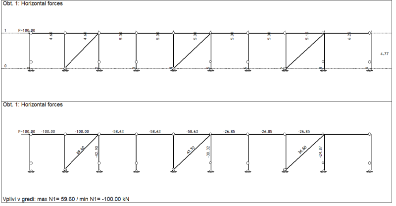
zavetrovanje_tnzlva.png
 
Replies continue below

Recommended for you

Well ..easy answer...the forces in a system are transferred according to stiffness
this is one reason why the horizontal force is not exactly 1/3 in each bracing


best regards
Klaus
 
Hi Mats, you answered your own question...with a question. "Does that mean that horizontal forces are destributed based on a stiffness of a single braced field?" It absolutely depends on the relative stiffness in each braced bay.

If you use all the same section for all of your braces, you should get pretty much an even split - all braces have approximately the same horizontal displacement at the top and they have the same stiffness, therefore equal split. The model may not give you a perfectly even split because the braces will have slightly different horizontal displacements due to the beams compressing slightly...but it should be pretty close to evenly split.

If you have different brace sizes, the lateral displacements will still be pretty much equal...but now most of the applied force is going to the stiffer braces.

 
Thanks for replies!

Well thats what I had in mind...but its also important where you actually put forces in a model...

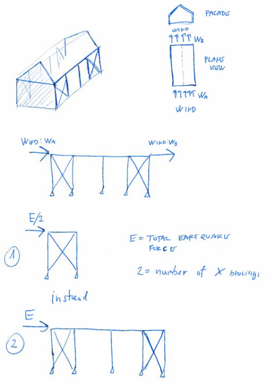
In a case of wind forces - I think its reasonable to put forces at the start and end of a frame since wind from face facades are transfered to a frame - similar will happen in real world.


But in a case of earthquake I think it should be transfered based on stifness like CANPRO elaborted and not how I modeled it 1st post. Putting a total earthquake force at the beginning of a frame is not what really happens. Results vary greatly. Since I have same sections for all braces/columns/beams and spans between columns are pretty much the same, I think I should devide total earthquake force with number of X bracings to get results that are more realistic.


bracings_uuam4y.png


EQ_ru1syp.png


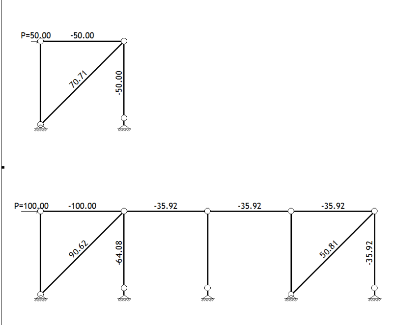
(90,62 + 50,81)/2 = 70,71 kN (so average force in tension diagonal in model 2 is the same as in model 1)
 
Well...basically the engineer need to have enough knowledge to do the 'correct' modeling
Computer program is just an aid....
You need to know that you expect from a model and according to that you have to define the INPUT so that the OUTPUT is usable
This is true for the model itself as well as for the boundary als loading conditions


best regards
Klaus
 
You may get results closer to what you expect if you apply a uniformly distributed axial load to the collector elements instead of a single point load at one or either end of the frame.

This would more correctly model how a diaphragm is distributing load anyways.
 
As bearjew stated (I both love your username and hate quoting it!), a uniform load would be more applicable; and this is probably more accurate as the wind load will actually get applied through your diaphragm
 
OK, that makes sense!
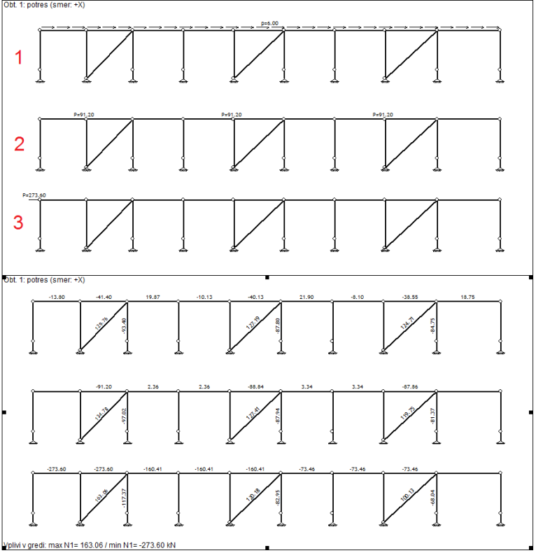
Im posting results for all three models for an actual problem. My total earthquake load on a frame is 273,60 kN. Since I have 3 X bracing that is 273,60/3 = 91,20 kN per bracing or in a case of uniform load that is 273,60 kN/45,60 m = 6,00 kN/m (lenght of a frame is 45,60 m).

MODELS:
1. total load as uniform load,
2. total load devided by number of X bracings,
3. total load at the start of the frame,

I think model 3 is the best.


123_mzerti.png
 
Can I ask why you've modeled the bracing columns with a pin at 1/4 point? Is that a splice? If all other columns are pinned at a splice, why not the one with the tension diagonal at the base?
 
Its just a picture software rendered. In reality they are all pinned at the bottom/support.
 
Ah, makes sense,

If it were me, and all things being equal, i.e. column spacing, column size, beam size, I would likely design it as option 2 and likely figure out the forces by hand. Are the braces modelled as tension only? are they allowed to be with seismic?
 
Yes, diagonals are for tension only, the other diagonals that are in compression are not considered in a model since they buckle in compression. Thats a standard bracing for steel portals in my country.

 
Said another way, the load distribution is all due to the stretching and squeezing of members along their longitudinal axis, be they columns, struts, or braces. The heavier you make your strut elements, the more even the distribution in the braces. If your struts are spaghetti, then all the load will go to the first brace.

You have to use your judgment when modeling to best (and most realistically) distribute the applied forces.
 
Status
Not open for further replies.

Part and Inventory Search

Sponsor