Continue to Site

Eng-Tips is the largest engineering community on the Internet

Intelligent Work Forums for Engineering Professionals

  • Congratulations GregLocock on being selected by the Eng-Tips community for having the most helpful posts in the forums last week. Way to Go!

Why is there a pully timing belt in this system before the encoder 2

Status
Not open for further replies.

Znjmech

Mechanical
Dec 19, 2016
94
Hi all

As you see in this following photo which is the driving system for a bottle filling machine, there's a set of gears run by an electromotor, that end up to a pully timing belt system that provides the machine position read for an encoder. my question is: if there are two or three gear to gear contacts before this pully, that can have an error. but when we get to the encoder we use belt to increase the rotating precision ? I feel something is missing or I don't know
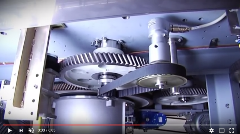
pully_thyeao.png
 
Replies continue below

Recommended for you

If you are asking why a belt was used instead of gears, it was probably because with gears the center to center distance is fixed and the encoder would not easily fit there. With a belt you can locate the encoder with much more freedom. Your picture makes it look like the encoder is floating in space.
 
Is the encoder part of the control loop for the motor? If so then, for control purposes, it may be better to have the encoder more directly hooked up to the motor than to the output shaft.

I agree that if the encoder is meant to monitor the output shaft then it's a bit of a waste, performance wise, to have a timing belt drive it when there are gears downstream.
 
Is there a link to the video?

It may be that the encoder is used as an input to some other part of the system to synchronize with the position of this shaft and that other gear errors don't matter.
 
We build a LOT of machines with encoders. In fact we build a lot of machines, and most of them have many encoders of various types. I can't recall ever driving an encoder directly with gears- they are always driven with a belt or a chain.

There's two factors at work that I suspect resulted in this belt-driven encoder arrangement:

1) There is gear error, but that gear error is very very small. Depending on the gearsets and how they're designed, you might have a rotational position error window that's anywhere between a couple of arcminutes, down to a few arcseconds wide. In a machine of that type, a rotational position error which does not compound and is only a couple of arcminutes wide simple doesn't matter. If positioning of the encoder is a challenge, using a train of gears could potentially increase the error, not reduce it.

2) Encoders on machines of this type are usually mission critical, and if a machine is well maintained, an encoder failure is one of the few things that can bring production to an immediate halt. Point is, encoders and their drives are designed so that they can be replaced as quickly as possible. That belt drive arrangement is much easier and faster to R&R than a train of helical gears would be.

The points made by other posters, such as packaging the encoder in the enclosure, etc are relevant as well.
 
Looking at the video, the encoder is driven by the output shaft. Clearly the position/speed of the output shaft is the most relevant. Using a timing belt ensures there is no backlash which would also be possible anywhere else on the geartrain.

je suis charlie
 
You mean that the backlashes on the gears aren't transmitted or are damped by the timing belt?
 
No. I mean that the encoder is reading output shaft position - there are no sources of backlash between the encoder and the output shaft.

je suis charlie
 
Status
Not open for further replies.

Part and Inventory Search

Sponsor