Continue to Site

Eng-Tips is the largest engineering community on the Internet

Intelligent Work Forums for Engineering Professionals

  • Congratulations IDS on being selected by the Eng-Tips community for having the most helpful posts in the forums last week. Way to Go!

Why line zero seq impedance & fault zero seq impedance are often regarded as 3x of positive seq 4

Status
Not open for further replies.

TS Liew

Electrical
Apr 27, 2020
25
Dear buddies,
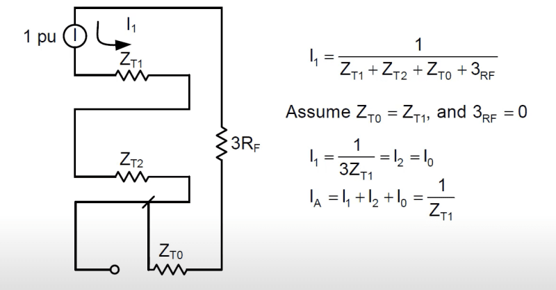
I hope to get some conceptual explanation on the above matter. Why line zero seq impedance & fault zero seq impedance are often regarded as 3x of its respective positive seq impedance.
Zero_seq_line_Zx3_uwzias.png


Thank you guys in advance.

TS Liew (Electrical testing, Commissioning, Power system studies)
 
Replies continue below

Recommended for you

In the sequence diagram it’s 3Rf because the current through it is only I0. The drop across it needs to be 3I0 * Rf. That’s the equivalent of I0 * 3Rf.
 

This is because of the mutual impedance influence and the coupling effect with the shield ground wires and the earth.

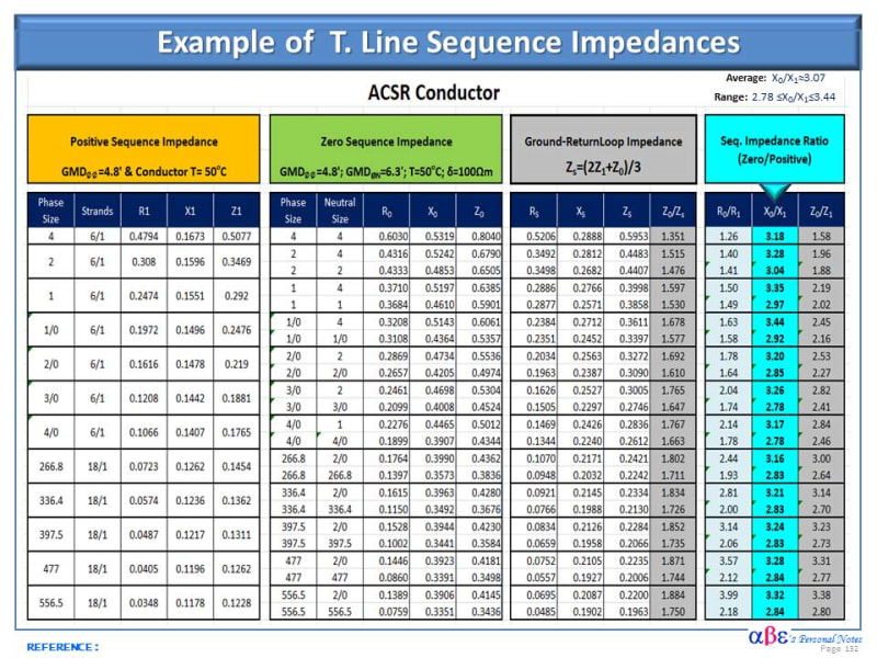
Technically speaking, the factor of 3 is a rule of thumb that can be used in the absence of actual data with some sacrifice inaccuracy and uncertainty values.

Often the T. Line Xo/X1 ≅ 3 on average ranging from 2 <X0/X1< 3.5.

The table below is an illustration of various T. Line data indicating the impedances and ratio between the zero to the positive sequence impedance values.

>>>>>
OH_T_Line_Sequence_Impedances_ex0nqc.jpg
 
Hi fellows,
Much thanks for your reply, both your reply immediately cracked open my understanding of the concept. Davidbeach's made the concept clear since a single fault to ground (solid earth) will carry 3 x Io, this make perfect sense to adjust the fault & line impedance to fit the zero sequence network to the positive & negative network that carries only 1 x Io. While
Cuky2000 response on mutual impedance and the line impedance ref. table gave me further practical ideas incorporating R and ground resistivity in design calculation.

Thank you.


TS Liew (Electrical testing, Commissioning, Power system studies)
 
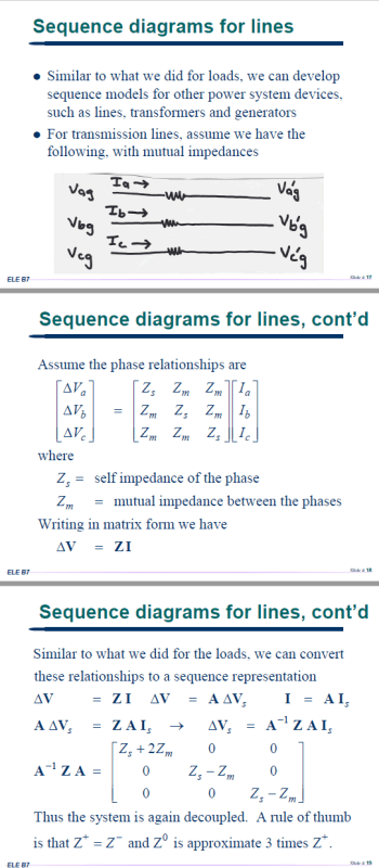
Since nobody provided the full derivation for lines yet, here is the math:

Line_Impedance_bwzznw.png


check out the last matrix. Zs + 2Zm is the effective zero sequence impedance. while Zs - Zm is the positive sequence. Zs is self impedance, Zm is mutual which goes back to culky's table.
 
Thank you protoslash for the update. This is great.

TS Liew (Electrical testing, Commissioning, Power system studies)
 
Dear protoslash, could you forward the link to the slides you posted?

TS Liew (Electrical testing, Commissioning, Power system studies)
 
@Cuky: what tower design are you using for those values? I've been looking for a table like that for a decade now, my satisfaction is innumerable.
 
@protoslash, much thanks for the link.

TS Liew (Electrical testing, Commissioning, Power system studies)
 
Hi MBrooke,

The impedance values on this table are for various line configurations used for distribution & sub-transmission tower & poles.

Should be noted as the voltage increases for HV and UHV, the relation still holds since the resistance to reactance ratio tends to be smaller as the systems voltage increases.

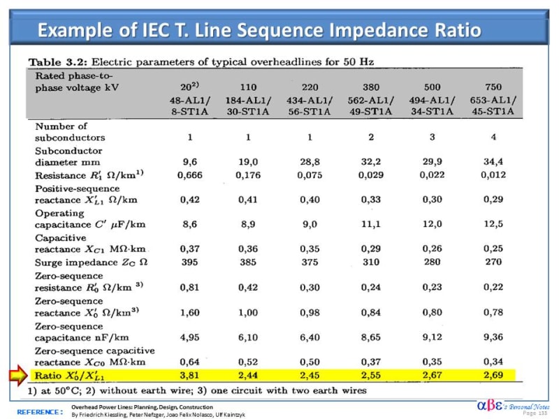
Below is another example of X0/X1 ration for various IEC tower configuration. It should be noted that the Xo/X1 ratio remains in the same range as mentioned earlier.

Two preliminary conclusions can be considered:
1) Appears that the X0/X1 ratio is less sensitive to the tower configuration.
2) It is also known that the number of shield wires significantly influences the Xo value but no X1, resulting in a higher Xo/X1 ratio as the number of shield wires increases.


T_Line_X0_to_X1_reactance_Ratio_qkfeoj.jpg
 
Status
Not open for further replies.

Part and Inventory Search

Sponsor