Hello,
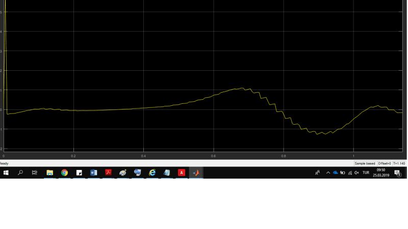
I modeled a simply pendulum mechanism in MSC Adams/View environment. I give the input angle values to the joint motion from matlab/simulink by using VARVAL(.MODEL_1.angle) command. I defined state variables and my outputs are torque, displacement and velocity x and y and accelereration. I readed this results from Simulink. My question is why it is not showing velocity and acceleration measurements in Simulink? It is showing displacements and torque values. Velocity measurement is done by VX(marker2) command.
I give the inputs in Adams environment instead of giving from Simulink. It gave me all measurement.
Why it is not giving velocity and acceleration values when i sent inputs from SİMULİNK.
Thank you for your consideration.
My file:

