Eng-Tips is the largest engineering community on the Internet

Intelligent Work Forums for Engineering Professionals

Wind Load and Foundation Design for Highway Lights 2

Status
Not open for further replies.

psychedomination

Structural
Jan 21, 2016
114
0
16
BM
Hi there,

I'm currently working on the foundation design for a traffic light structure. I am in a hurricane-prone region; I ran the numbers for two scenarios (173 and 144 mph wind speeds). However, I have a few questions regarding the wind analysis approach and the foundation design approach. My calculations are attached :

For the wind load :

I carried out the wind analysis as per ASCE 7-10 for solid signs. Is this a suitable approach for traffic lights too?

Based on the calculations, am I being too conservative regarding the assumed area of the traffic light being hit by the wind?

For the foundations :

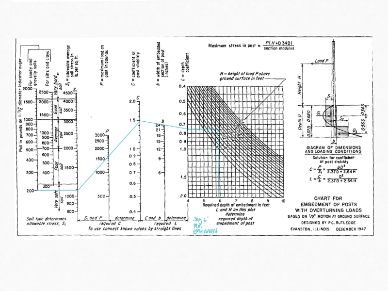
I was looking to use a drilled shaft foundation and for the analysis, I used the IBC 2012 eq 18-1 (I don't have geotechnical information regarding the lateral capacity of the soil, I just know that based on images of previous excavation works that it appears to be a granular sand/sandstone type material, so this method seemed ideal vs others which appeared to require input from a geotechnical report). Is this suitable or should I have used a different approach?

The final embedment depths that I am getting are very large. For a 10' tall pole I'm getting an embedment depth of ~10' for the 173mph wind speed case and ~7' for the 144mph wind speed case. Does this seem reasonable?

I tried to do a sanity check by comparing my results against the Florida DOT typical details (as I believe that they are hurricane-prone as well). However, for a similar structure, they are only specifying 3' depths and 4' depths, which has me thinking that I am doing something incorrectly. See FDOT typical detail links below :

Link

Link

Any help or guidance would be greatly appreciated!


 https://files.engineering.com/getfile.aspx?folder=ac68b860-68f7-4638-bdbd-561e4024411b&file=Traffic_Lights.jpg
Replies continue below

Recommended for you

What is the diameter of your footing? I can't tell from your area calcs.

I did a quick calc in enercalc with your forces and got around 7' required for the 177 mph wind but with a 3' diameter pile. Your calcs don't seem that far off to me!

I think your area for wind is definitely a little conservative, maybe decrease by 25% versus the full rectangular area.. Keep in mind that the top of your pile will also likely be restrained with well compacted fill or likely a sidewalk, which will help out a lot and give some unknown factor of safety.
 
Thanks Jeb, that is helpful. The foundation diameter I used was also 3'.

I always get a bit anxious about these types of designs and how to deal with clients/contractors who complain about the depths.

That's also true about the potential sidewalk restraint.
 
AASHTO has a guide document, "Structural Supports for Highway Signs, Luminaires and Traffic Signals." I looked online, and there is a cost to obtain it.

So...if you don't have need for this on a regular basis, I think what you have done is appropriate. However, IBC Equation 18-1 is very conservative. If you are going to use it, make sure you double the allowable lateral soil pressure, as is permitted, if the drilled shaft can move 1/2" at grade.

Alternatively, there are hand methods like the P-y method, or programs like L-Pile, which can design a drilled shaft for lateral loads. My guess is these methods will be less conservative than IBC.

DaveAtkins
 
Another thing to note is that AASHTO usually isn't as strict when it comes to wind design. They just provide some blanket design numbers and move on for most structures. It might well be worth the cost to buy the book referenced above.
 

It does not seem reasonable to me. I just screened your calculation and apparently there are some mistakes.

- The subject depth formula ( eqn 18-1) is a closed form formula and needs some iteration. Pls look the term A=2.34P/(S1*b)and S1 is allowable lateral earth pressure based on 1/3 depth of embedment.

- You do not know initially the depth of embedment so , try a depth say 6 ft ,
- then calculate the allowable lateral earth pressure based on 1/3 depth (2 ft) of embedment S1= 200*2=400 psf . Pls look to the table 1806-2 The lateral bearing pressure is for 1 ft nominal depth ( for total 3 ft embedment ), in your case the first iteration 6 ft so multiply 200 psf mit 2.0

- Find the new depth for presumptive 6.0 ft depth , and repeat the same procedure till new depth and reasonably equal to the previous iteration,
- You may also use alignment charts .
- Calculate the depth in ft using (lb- ft ) units then change the unit if necessary

Good luck.

EDIT; This subject discussed a few times and one of them ( Origin of Drilled Post Foundation Equations in IBC 3
thread194-514629 ) You will see the alignment chart at my respond.


Use it up, wear it out;
Make it do, or do without.

NEW ENGLAND MAXIM


@HTURKAK Thanks this is very helpful.

I redid the calcs using the revised approach of increasing the soil lateral capacity by 1/3 preliminary embedment depth. I also doubled the lateral soil capacity to allow for a 1/2" deflection.

I'm assuming this is the approach you mention? (See attached calcs)

If so, it appears that a minimum embedment of 4.61' will work for the 173mph wind load case with a 3' diameter shaft.

I also took a look at the alignment tables that you shared in your linked post. It appears that these tables only go up to 2' diameter shafts/poles? In my case I was looking at a 3' diameter shaft, however, the tables do appear to be helpful for quick embedment calcs.

One thing I was uncertain of with in the embedment tables were the S1 values (allowable average soil stress). How are these values determined? I'm unfamiliar with the "pull in lbs with auger" terminology, is that value required to determine the S1 values?

When I attempted to use the graph,I believe my S1 assumption may be incorrect. But I would like a better understanding of this for future projects. See below :

Embedment_Graph_-_Copy_uzgddy.jpg


Per IBC Table 1806.2, the allowable lateral bearing pressure for sand is 150 psf per foot depth. For a depth of 2', this results in 300 psf. Multiply by 2, since you are allowing movement at grade, and S1 = 600 psf.

DaveAtkins


Q=I'm assuming this is the approach you mention? (See attached calcs)
A= Yes but the units of original formula (ft-lb-sec) . I suggested to use Lb-ft then convert to SI units if necessary. I did not check if the subject formula can be used for SI units but my opinion , the formula is valid for Lb-ft units.

Q= If so, it appears that a minimum embedment of 4.61' will work for the 173mph wind load case with a 3' diameter shaft.

A= I posted hand calculation for 1589 lb force and 5 ft embedment is OK .


Q = . It appears that these tables only go up to 2' diameter shafts/poles? In my case I was looking at a 3' diameter shaft, however, the tables do appear to be helpful for quick embedment calcs.
A= TRUE..

Q= One thing I was uncertain of with in the embedment tables were the S1 values (allowable average soil stress). How are these values determined? I'm unfamiliar with the "pull in lbs with auger" terminology, is that value required to determine the S1 values?
A= Acc. to geotechnical report but typical poor or average soil safe bearing stress should be 2000 lb-sf. There is a worked example at my post . thread194-514629: Origin of Drilled Post Foundation Equations in IBC )

Good luck..


Use it up, wear it out;
Make it do, or do without.

NEW ENGLAND MAXIM


 https://files.engineering.com/getfile.aspx?folder=6c9d3c15-2b0c-4e85-8956-9437a68cd99e&file=EQUATION_18-1.jpg
Status
Not open for further replies.
Back
Top