Continue to Site

Eng-Tips is the largest engineering community on the Internet

Intelligent Work Forums for Engineering Professionals

  • Congratulations pierreick on being selected by the Eng-Tips community for having the most helpful posts in the forums last week. Way to Go!

Wind load on roof ridge beam

Status
Not open for further replies.

m1208

Structural
Apr 6, 2011
69
I have a roof ridge beam that spans 27' with tributary width of 10.5'. The house is one-story and the roof height at the ridge is 15'. The wind has exposure C with 85 mph wind. Based on the ASCE tables, the down wind load is 7 psf and the upward wind is 32 psf. I am getting a high uplift at the end connection of the beam due to the uplift wind load combination. Any idea why the uplift wind is so high, 32 psf? I have attached a sample calculation for reference.


WIND LOADS

WIND LOADING ( ASCE 7)
COMPONENTS AND CLADDING , METHOD 1
ENCLOSED BUILDING
EXPOSURE C
BASIC WIND SPEED, V 35, 85 MPH
ROOF ZONE 2, ASCE FIG 6-3 (CORNER ZONE, CONSERVATIVE)

Ps = λ Kzt Iw Pnet30
λ = 1.21 (EXPOSURE C, ROOF MEAN HEIGHT =15', FIG 6-2)
Kzt = 1.0 (AISC SECTION 6.5.7.2, FLAT TERRAIN)
I w= 1.0 (TABLE 6-1, ASCE 7-05, CATEGORY II)
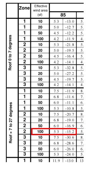
Pnet30 = + + 6.0 AND - 26.0 7 < ANGLE < 27 , ZONE 3, EFFECTIVE AREA 27'X10.5'
Ps Down = 1.21 x 1.0 x 1.0 x 6.0 = 7.3 PSF
Ps Up = 1.21 x 1.0 x 1.0 x 26.0 = 31.5 PSF

NOTE:
THE WIND LOAD IS NORMAL TO THE SURFACE OF THE ROOF. WE ARE USING THE HORIZONTAL
LENGTH FO THE ROOF MEMBER FOR CALCULATION. THEREFORE, WE INCREASED THE WIND
LOAD TO COMPENSATE FOR THE HORIZONTAL LENGTH OF THE MEMBER.
(1/COSINE 18)
Ps Down = 7.3 PSF x 1.05 = 7.6 PSF
Ps Up = 31.5 PSF x 1.05 = 33.0 PSF

 
Replies continue below

Recommended for you

Which edition of ASCE 7? there are many.


Check out Eng-Tips Forum's Policies here:
faq731-376
 
Hi:
I am using ASCE 7-05.
 
Can this roof be analyzed as if it was a folded plate? If so, you look more to anchoring down a sail.
 
I never use ASCE's "simplified" method. But, the results look reasonable for a corner wind zone. The reason the results seem high is because the corner wind zone is being used for the entire roof. If I remember correctly, the simplified method's C&C wind pressure is normal to the roof surface, so the vertical component at the ridge connection will be less.
 
What is the roof pitch?

Should you not be using the vertical component for uplift rather than the horizontal? The net uplift should be less than the normal force to the rafters. Subtracting the dead load of the roof, I can see an uplift of 2K at each end. One strap should be able to handle that.

Mike McCann, PE, SE (WA)


Yes 4:12 is a kind of standard roof pitch for residential homes in this area.
 
Not sure where you are getting the 26 psf.
Most of your ridge beam would be in zone 2 with the ends of the ridge beam zone 3.

Your area is more than 100 sf.
aaaamethod_1_z9znyb.jpg


This results in 1.21 x 15.2 = 18.4 psf uplift along the interior length of the ridge and
1.21 x 24 = 29 psf uplift on the ends for a distance "a".

Check out Eng-Tips Forum's Policies here:
faq731-376
 
JAE...the trib. area for zone 3 (a=4') would probably be about 40 sf rather than 100, thus by interpolation, 26.9 x 1.21 = 32.5 psf.....doesn't make much difference, though.
Just jumped into this one so square me up if I missed something!
 
a is usually only 6 to 8 feet or so, not the whole ridge beam length.

Mike McCann, PE, SE (WA)


I don't think you calculate the effective wind area based on "a" but rather the full span of the ridge beam (27 ft.) and its tributary area.
The effective area is all about the beam and not the zones, right?
All that the dimension "a" does is define where 3 ends and 2 begins.


Check out Eng-Tips Forum's Policies here:
faq731-376
 
Thanks for all the good points. One question I still have is when do I you fig 6-2 and when do I you use fig 6-3? My understanding is that for the design of the components, such as roof ridge beam, I use fig 6-3. I use fig 6-2 for the overall analysis of the building. If I want to find the uplift at the end of the roof truss connection to the exterior wall, do I use fig 6-2 or fig 6-3?
 
JAE...I'm confused.

You have a ridge beam that is 27 feet long. It has a tributary area of 10' x 27', but part of that tributary area is in Zone 2 and part is in Zone 3.

The part in zone 2, has a wind loading of x ((27-2a) x 10) x W). The part in zone 3 has a wind loading of y ((a x 10) x W) for each end). Each is treated separately.
 
Ron - your calculations are exactly correct.

My point is that for the beam, there is ONE effective area to use in determining the wind pressures.
You don't enter that table with a x 10 to find the zone 3 pressure and (27-2a) x 10 to find the zone 2 pressure.
Look at my red box in the table above. The pressures are based on >100 sf because the beam has >100 sf of tributary (effective) area involved.

So the 26 psf that the OP used - not sure where it came from - there is a 26 psf for zone 3 at 50 sf but for >100 sf it should be 15.2 or 24 psf for 2 and 3 respectively.


Check out Eng-Tips Forum's Policies here:
faq731-376
 
Trenno said:
1:3? Haha

The "yanks" like to relate roof pitch in units of 12, with 12 being the horizontal unit of 1 foot (12") - given the imperial (non metric/SI) system of units. It makes the math easy, I guess.

The first time I heard a term 2:12, or 4:12 I did the same as you...convert it to 1:X.
 
Status
Not open for further replies.

Part and Inventory Search

Sponsor