Eng-Tips is the largest engineering community on the Internet

Intelligent Work Forums for Engineering Professionals

  • Congratulations waross on being selected by the Tek-Tips community for having the most helpful posts in the forums last week. Way to Go!

Wiring alternative for 3-phase heating circuit to reduce current 7

Status
Not open for further replies.

PaulKraemer

Electrical
Jan 13, 2012
145
0
0
US
Hi,

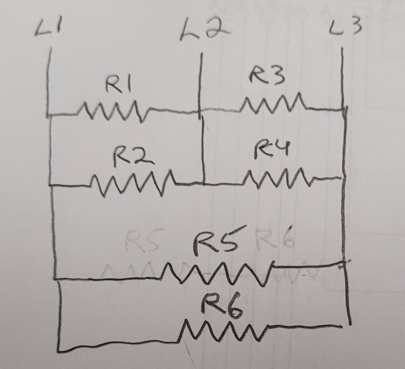
I have a tank that is used to melt glue. It has six heaters, each with a resistance of 10 ohms. It is powered with 208 VAC three phase.

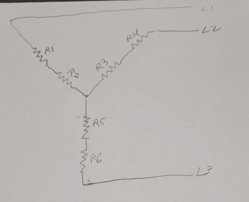
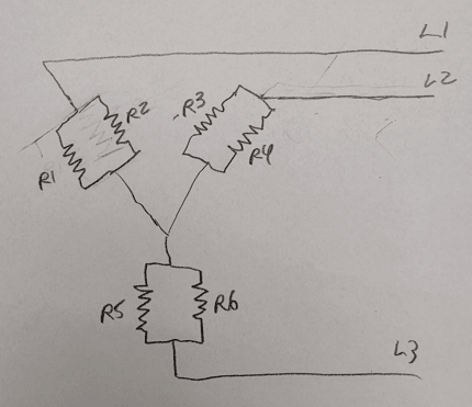
Originally, it was wired as shown below with two heaters in parallel across each possible pair of lines (L1-L2, L2-L3, and L1-L3)...
Parallel_mwpoly.jpg


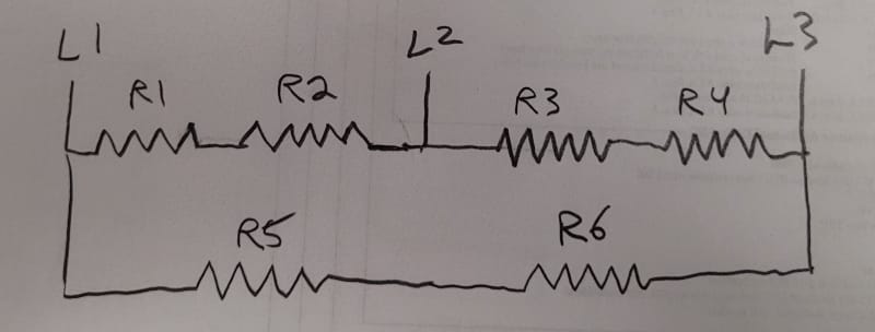
I had asked a question yesterday about how to calculate the total current that this circuit would draw from L1, L2, and L3, which turned out to be about 72 amps. It turns out that this exceeds the rating of the breakers I have available to feed this circuit. With this being the case, I considered rewiring the heaters as shown below to reduce the current draw ...
Series_jphkjt.jpg


... When I did the same current calculations (if I did them correctly), this decreased my expected current by a factor of four (down to 18 amps). This would make it easy for me to find a breaker to serve the circuit, but I am afraid that the corresponding factor of four decrease in heating power might make me unable to melt glue at my required rate.

I am wondering if anyone here can suggest another wiring alternative that would allow me to decrease the current draw by a factor that is less than four while still keeping my load balanced and having the same current flowing through every heater. I though about simply eliminating three heaters so that I would only hava a single heater across each possible pair of lines (L1-L2, L2-L3, and L1-L3), but I don't like this idea because it would mean I would then have less heated surface area in contact with the glue. I would really like to have current (albeit reduced) flowing through all six heaters. With six heaters and three lines, I just can't think of a way I can do this other than how I show in my second diagram (which results in a 4x reduction in power).

Any suggestions will be greatly appreciated.

Thanks and best regards,
Paul
 
Replies continue below

Recommended for you

Eliminate R2, R4, and R6. That will reduce your load by 50%.
Go to a wye connection. That will reduce your load by 67%.
Bill
--------------------
Ohm's law
Not just a good idea;
It's the LAW!
 
Dear Mr. PaulKraemer (Electrical)(OP)4 Aug 21 14:12
"... It has six heaters, each with a resistance of 10 ohms. It is powered with 208 VAC three phase. Originally, it was wired as shown below with two heaters in parallel across each possible pair of lines (L1-L2, L2-L3, and L1-L3)..."
1. I am thinking by connecting [R1, R2 in series]; [R3, R4 in series], [R5, R6 in series]. Connect R1 to L1, R3 to L2, R3 to L3. Connect R2,4,6; in Y formation. This formation will result to [the lowest current] but check whether the heat produced (wattage) is sufficient to melt the glue.
2. Alternatively, R1, R2 in parallel, R3//R4, R5//R6. Connecting to the L1,2,3 ; in Y formation. This will produce more heat or higher (temperature).
3. Note: to achieve the heat you required:
a) it would required a certain current (amperage) with a fixed voltage supply source; no matter how you connect the heaters.
b) the [electricity bill] remains the same i.e. electrical power (wattage) input = heat output.
Che Kuan Yau (Singapore)


Hi Che -

Thank you for your suggestions. For the two options you mentioned (which I repeated below in italics), can you please let me know if the sketches I have inserted beneath each one accurately reflects what you have in mind? ...

1. I am thinking by connecting [R1, R2 in series]; [R3, R4 in series], [R5, R6 in series]. Connect R1 to L1, R3 to L2, R3 to L3. Connect R2,4,6; in Y formation. This formation will result to [the lowest current] but check whether the heat produced (wattage) is sufficient to melt the glue.

Option_1_dwtryd.png


2. Alternatively, R1, R2 in parallel, R3//R4, R5//R6. Connecting to the L1,2,3 ; in Y formation. This will produce more heat or higher (temperature).

Option_2_ewh7ri.png


I appreciate your help with this.

Thanks again and best regards,
Paul
 
Voltage (208 Volts) times Amperage times the root of three (1.73) will give you the heat produced in Watts.
If you connect three resistors in delta and three resistors in star, calculate the Watts of each group and then add. That is much easier than trying to figure the resulting sum of currents at different phase angles.

Bill
--------------------
Ohm's law
Not just a good idea;
It's the LAW!
 
Compared to the heaters in parallel and delta, the delta connection will produce 50% of the original Watts.
Compared to the heaters in parallel and delta, the star connection will produce 28.9%% of the original Watts.
The total wattage of this connection will be 78.9% of the original wattage.
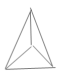
image_fpaje0.png


This is an interesting connection:
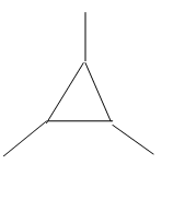
It will reduce the total wattage. How much reduction? I will leave the solution of that to my friend ElectricPete.
If I was to solve, I would start with a stated phantom current and work backwards to a voltage. I would then scale the voltage and current to match the 208 Volts.
image_t21cmb.png


Bill
--------------------
Ohm's law
Not just a good idea;
It's the LAW!
 
That last connection: yowzer!

I'd probably "solve" that by wiring up six 100 W incandescent bulbs to a 208 V three phase supply and measuring and recording the voltages across all six resistors - and I'm intuiting that the bulbs would not blow.

Once the relationships and values of voltages are known, the current flowing in each resistor can be derived by scaling up, as the voltages relationships will not change.

Even thinking of trying to figure out how I would calculate the values mathematically / trigonometrically is making my head hurt . . .

CR

"As iron sharpens iron, so one person sharpens another." [Proverbs 27:17, NIV]
 
Here are the calculations for the various configurations of six equal heater elements in a balanced three-phase system. The last two calculations listed are for waross's final two sketches above, a delta with an internal wye and a wye with an internal delta. The trick for these two is to use balanced wye-delta and delta-wye conversions, respectively, to come up with equivalent resistances, then see that they are in parallel or in series. I came up with different power percentages of waross's base power, though. I'd appreciate it if someone checked to see if I made any mistakes. I don't think I did; I checked all configuration calculations with LTSpice.

xnuke
"Live and act within the limit of your knowledge and keep expanding it to the limit of your life." Ayn Rand, Atlas Shrugged.
Please see FAQ731-376 for tips on how to make the best use of Eng-Tips.
 
 https://files.engineering.com/getfile.aspx?folder=c1042892-a35b-4add-8bee-4440e9263333&file=Three-Phase_Heater_Calcs.pdf
Dear Mr. PaulKraemer (Electrical)(OP)5 Aug 21 17:23
" ... For the two options you mentioned (which I repeated below in italics), can you please let me know if the sketches I have inserted beneath each one accurately reflects what you have in mind? ... "
" ...1. I am thinking by connecting [R1, R2 in series]; [R3, R4 in series], [R5, R6 in series]. Connect R1 to L1, R3 to L2, [highlight #CC0000]R3[/highlight] to L3. Connect R2,4,6; in Y formation. This formation will result to [the lowest current] but check whether the heat produced (wattage) is sufficient to melt the glue...."
My apology, there is a typo error. It should be...Connect R1 to L1, R3 to L2, R5 to L3. I noticed you had got it right. It was my mistake that had caused the confusion. I am sorry for the inconvenience caused.
2. The second drawing, with resistors in parallel is in order.
Che Kuan Yau (Singapore)


I'd love to spend a day sharing stories and drinking coffee with you CR.
How is this solution:
5 Ohm resistor in the delta with 208 Volts three phase applied to the delta. 41.6 Amps.
Current to a corner of the delta = 72 Amps.
5 Ohm resistor at 72 Amps = 360 Volts.
Voltage from the delta corner to a calculated electrical neutral = 120 Volts. (This aligns the angle of the delta voltage with the angle of the wye voltage)
Total line to neutral voltage = 120 V = 360 V = 480 Volts
Edit: I forgot the root. 480V x 1.73 = 831.4 Volts, phase to phase.
480V / 208V = 2.308
831.4V/208V = 3.997. or 4.
All currents and voltages may be scaled by 1/2.308 or multiplied by 0.433
All currents and voltages may be scaled by 1/4 or multiplied by 0.25
Line current = 72 Amps / 4 = 18 Amps
Does that work for us, CR?

Bill
--------------------
Ohm's law
Not just a good idea;
It's the LAW!
 
(Into microphone) Is this thing on?
Please see my previous post (including the linked file) for a much easier solution, Bill and CR. It confirms 18 A is correct.

xnuke
"Live and act within the limit of your knowledge and keep expanding it to the limit of your life." Ayn Rand, Atlas Shrugged.
Please see FAQ731-376 for tips on how to make the best use of Eng-Tips.
 
Dear Mr. PaulKraemer (Electrical)
1. There are numerous ways of connection the 6 resistors (heater). They can be connected in series, parallel, in Y , D or YD formation etc.
2. I tried to work out four basic connections based on the resistor each rated 208V 10 Ohm on a 3ph 208V source.
2.1 in Y formation:
a) 2 resistors in series (10+10)=20 Ohm.
Line current = 6A . Total power of 6 resistors = 2161.5W
b) 2 resistors in parallel (10//10)=5 Ohm.
Line current = 24A . Total power of 6 resistors = 8647.2W
2.2 in D/b] formation:
a) 2 resistors in series (10+10)=20 Ohm.
Line current = 18.01A . Total power of 6 resistors = 6488.21W
b) 2 resistors in parallel (10//10)=5 Ohm.
Line current = 72.05A . Total power of 6 resistors = 25958.4W
3. Observation:
a) No matter in Y, D or YD formation, resistors in series or in parallel connection; the (line current) is proportional to the [heat generated].
b) The (electricity bill) is proportional to the [heat generated].
Che Kuan Yau (Singapore)
 
b) The (electricity bill) is proportional to the [heat generated].
Or
Unless and until the higher wattage triggers demand charges.
And less frequently
When paired with an inductive load a lower resistive load will be less buffering of the VARs of the inductive load and may trigger power factor penalties.
And that is not to mention non linear tariffs.
Actually, over the years, I have seen very few tariffs where the cost of electricity was directly proportional to the heat generated or the kilo-Watt-hours used.
The heat generated is proportional to the kilo-Watt-hours consumed.

Bill
--------------------
Ohm's law
Not just a good idea;
It's the LAW!
 
I realized I used the wrong resistance in my previous calculations. The file linked below is now correct.

Thanks to che12345 for providing comparison calcs.

xnuke
"Live and act within the limit of your knowledge and keep expanding it to the limit of your life." Ayn Rand, Atlas Shrugged.
Please see FAQ731-376 for tips on how to make the best use of Eng-Tips.
 
 https://files.engineering.com/getfile.aspx?folder=e808422a-b07a-447c-a51a-040ed25a9c41&file=Three-Phase_Heater_Calcs.pdf
I'd love to spend a day sharing stories and drinking coffee with you CR.

Hi Bill, part of me wants to say, "Next time we plan to head BC/Alberta way, let's set something up."

The other part of me is thinking, "Eek! Face to face, Bill will find out how truly vast my ignorance is."

Hmmm, decisions, decisions . . .

Tell you what: next time my wife and I plan to head BC/Alberta way, let's you and I set something up.

CR

"As iron sharpens iron, so one person sharpens another." [Proverbs 27:17, NIV]
 
P = V x I, so anything you do to reduce I will reduce the P, i.e. make less heat.
Less heat in a melting application means it will take more time to achieve the melt temperature, plus you run into the possibility of the heat losses in the melt vessel leaving you with never fully achieving it, i.e. your losses are faster than the heat gain at the lower wattage. So if you do reduce the heat to reduce the current, find a way to reduce thermal losses in your vessel.

Why do I say this? Been there, done that, got the T-shirt and the hat...


" We are all here on earth to help others; what on earth the others are here for I don't know." -- W. H. Auden
 
I had one go the other way, Jeff.
A large liquid CO2 vessel. 2000 to 5000 gallons, and a set of heaters to vapourize the liquid.
During startup the process engineers couldn't get their pressure up. They hatched a plan to reconnect the heaters for more heat.
They asked me to reconnect the heaters for more heat. They felt that even at overvoltage, the heaters would not burn out as long as they were immersed in liquid CO2.
I did what they asked and reconnected for three or four times the heat.
They still could not get their pressure up.
They eventually discovered that someone had left a 1" purge valve open at the far end of the plant.
Once they closed the valve and quit venting to atmosphere, the pressure came up just fine.
I've seen the open valve syndrome more than once on startups.

--------------------
Ohm's law
Not just a good idea;
It's the LAW!
 
If you want the same heat, then your mains power will be the same, regardless of how you wire it, PERIOD. If you don't want to blow the breaker, then you need another circuit from a different breaker, or upgrade the existing circuit/breaker, PERIOD. There's nothing magical about the connections.

TTFN (ta ta for now)
I can do absolutely anything. I'm an expert! faq731-376 forum1529 Entire Forum list
 
Status
Not open for further replies.
Back
Top