Continue to Site

Eng-Tips is the largest engineering community on the Internet

Intelligent Work Forums for Engineering Professionals

  • Congratulations SSS148 on being selected by the Eng-Tips community for having the most helpful posts in the forums last week. Way to Go!

wood beam + steel (bolted together) 3

Status
Not open for further replies.

n3jc

Civil/Environmental
Nov 7, 2016
189
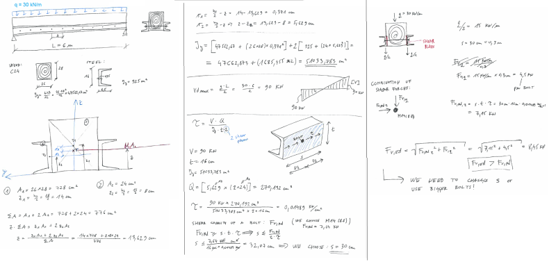
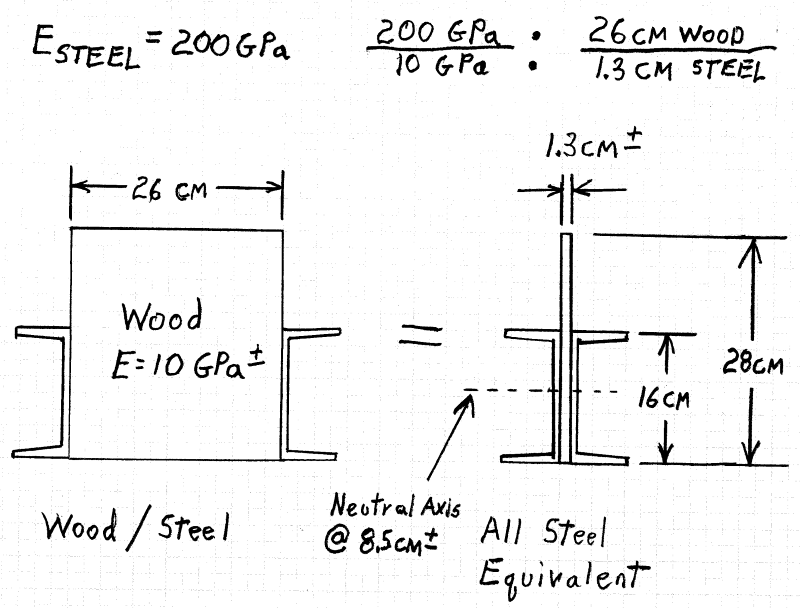
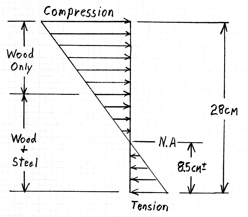
I have a wood beam reinforced with steel, connected by steel bolts.
The load is applied on wood beam only.
The load is transfered through bolts (2 shear planes) to steel.
Friction between wood/steel is not considered.
I also assumed, that the whole load is transfered to the steel sections (I did not calculate the load transfering to steel - by ratio of the stiffness).

Im wondering if this calculation is OK?
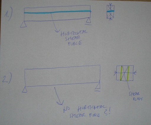
I was expecting bolts closer to each other. I do not think bolts that far apart are sufficient connection for this to be a composite (one element)?
What am I missing?
 
 http://files.engineering.com/getfile.aspx?folder=fcd8b1a4-13bb-4400-a790-81e7023a113f&file=BEAM_STEEL_WOOD.png
Replies continue below

Recommended for you

You've only transferred the vertical shear across to the channels. For composite action, you'll also need to transfer horizontal shear with a VQ/I calculation.

I like to debate structural engineering theory -- a lot. If I challenge you on something, know that I'm doing so because I respect your opinion enough to either change it or adopt it.
 
Do you actually want this to be a composite section or can the channels do the job on their own? If it's the latter and you've got adequate deflection control, your call would be fine. Getting good composite action with something like this is tough due to the inevitable slip in the bolt holes.

I like to debate structural engineering theory -- a lot. If I challenge you on something, know that I'm doing so because I respect your opinion enough to either change it or adopt it.
 
You don't need composite action per your OP, the steel handles 100% of the load. The wood only has to transfer the force so....

force goes into wood connection (face mount hanger). then wood transfers it to bolt locations. then bolt transfers connection through wood bearing and steel bearing to steel beam. Obviously there are other checks at each load transfer but this is only a path. No composite action calculated or needed if the steel does all the span work.
 
@KootK - i dont believe there is any horizontal shear there - just like in flitch beams... i think there would be a horizontal shear if you have an element on top of another, but not by the side like in this case. If there is horizontal force can you tell me where does it occur?

DSC02072_h9orq3.jpg


Channels dont do the job on their own. But if they would - wood beam wont be really needed (only for basis - let say for rafters)

I want it to be a composite section, because deflection and shear is a problem. Beam is 5,5 m long.

The deflection is fine if this is actually a composite (transformation method - all elements are the same material).

I really dont see how this is different than flitch beams. its pretty much the same problem/design. But with flitch beams we have a composite (no horizontal shear, just transforming vertical load by bolts to steel and its a composite). Something is missing...

fb_jhqbuk.jpg
 
n3jc said:
I really dont see how this is different than flitch beams. its the same design. But whith flitch beams we have a composite (and no horizontal shear, just transforming vertical load by bolts to steel). Something is missing...

Usually a flitch beam will have the centroids of all of the plies aligned vertically or close to it. In that scenario, you're right, there is no horizontal shear. However, once the centroids of the various plies are offset, as with your channels, there is horizontal shear.

Think of if like this:

Most of the benefit of your reinforcement comes about because you'll have an axial tension in your channels to help resist moment and curvature of the composite section. How would that axial force get into the channel other than through little horizontal forces delivered to it at each bolt? Those little horizontal forces = horizontal shear transfer.

I like to debate structural engineering theory -- a lot. If I challenge you on something, know that I'm doing so because I respect your opinion enough to either change it or adopt it.
 
Good post, tnx!

Ok, I understand what you try to tell me, but how can i calculate this? How to get an axial force in chanels - axial force is actually a shear load that needs to be taken care of by sufficient bolts and bolt spacing. Right?
 
Question on Shear Flow calculation
If the bolts are 16" o.c. top and bottom staggered as is usual, do you consider the spacing to be doubled (32") for distance in q =(VQ)/(Ixx t) where t = distance between bolts.
 
KootK - Are you saying that the channels are in tension because they're on the bottom half of the cross section? If they were raised to have their centroid above the centroid of the wood, would the primary benefit come from compression in the channels?
 
n3jc said:
Good post, tnx!

You're very welcome. It's great that you're as receptive to new ideas as your are. Not everybody is.

In detail, it's actually quite a complex thing. Each bolt carries both a horizontal and vertical shear force with the horizontal force increasing towards the ends. Most designers will design for one or the other but rarely both. And, in many instances, that's fine as one of the forces typically dominates. Aligned centroids sort of being the extreme example of that: all vertical, no horizontal.

n3jc said:
but how can i calculate this? How to get an axial force in chanels - axial force is actually a shear load that needs to be taken care of by sufficient bolts and bolt spacing. Right?

Exactly. You calculate it by doing the same VQ/I calculation that you'd do if the shear planes were horizontal. In your case, Q will be based on each individual channel.

You'll also have to run the calculation using using a transformed area cross section to account for the fact that your steel is stiffer than your wood. You could just convert your channels into equivalent wood rectangles, maintaining the height and vertical location of the centroid but allowing the width to expand.

I like to debate structural engineering theory -- a lot. If I challenge you on something, know that I'm doing so because I respect your opinion enough to either change it or adopt it.
 
tnx guys! helped a lot. will look into this
 
TheDayWalker said:
KootK - Are you saying that the channels are in tension because they're on the bottom half of the cross section? If they were raised to have their centroid above the centroid of the wood, would the primary benefit come from compression in the channels?

Yes and yes as kingnero said. Technically, the channels experience both axial force and bending. For OP's proportions, I expect it to skew towards primarily axial which, of course, is evidence of efficient reinforcing, at least in the material sense if not the economic.

Placing the channels on the compression side would lower the wood tensile stresses some but, as kingnero mentioned, it wouldn't be very efficient.

PT999 said:
If the bolts are 16" o.c. top and bottom staggered as is usual, do you consider the spacing to be doubled (32") for distance in q =(VQ)/(Ixx t) where t = distance between bolts.

I usually use VQ/I to get a lb/ft and then supply enough bolts to resist that, utilizing both of the staggered rows. Does that answer your question? I suspect that your formula is an adaptation that I'm not familiar with. In yours, is q the force per bolt?

I like to debate structural engineering theory -- a lot. If I challenge you on something, know that I'm doing so because I respect your opinion enough to either change it or adopt it.
 
Staggered Bolt Question
q is shear force per unit length tau (usually inches in US customary
So your answer is that the bolt spacing is not doubled for top and bottom staggering. Is that right?
 
What do you guys think about my calculation?

beam_calculation_ffsuup.png
 
PT999 said:
q is shear force per unit length tau (usually inches in US customary
So your answer is that the bolt spacing is not doubled for top and bottom staggering. Is that right?

I'm still confused by the equation. For a lb/in shear value, there would be no "t" in the equation. It would be just VQ/I. With "t" in there, the units of the result would be stress.

I'll calculate a VQ/I (lb/in) for the channel, divide that by the number of bolt rows, and then multiply by the bolt spacing in each row to get the force on each bolt.

I like to debate structural engineering theory -- a lot. If I challenge you on something, know that I'm doing so because I respect your opinion enough to either change it or adopt it.
 
n3jc - There is a problem with your calculation of the location of the neutral axis. KootK mentioned that the steel is usually transformed into equivalent wood section - this was not done in the calculations. In this case, it is easier to transform the wood into an equivalent steel section. The neutral axis is going to be located at an estimated 8.5 + cm, not at 13.6 cm. See the diagram below:

Equivalent_Steel_j7gcrr.png


The diagram gives a clue to another problem - there is not enough steel in the compression area of the composite beam. Compression bending stress is going to be more than double the tension bending stress... and the only material located to resist it is wood. I have not performed the calcs, but you should. IMHO, any significant loading of the composite beam will have the wood overloaded / failing in compression.

Bending_Stress_wfhnwj.png


[idea]
[r2d2]
 
I think that you could reduce your vertical bolt forces a good deal with a more accurate estimate of the vertical force being transferred. Looking at the vector sums in your calc, however, it appears that the difference would be small.

I like to debate structural engineering theory -- a lot. If I challenge you on something, know that I'm doing so because I respect your opinion enough to either change it or adopt it.
 
SlideRuleEra yes, there is mistake in my calculation when calculating position of centroid. An entire cross section has to be from the same material, so you need to do it on transformed section (all steel in this case). You need this when checking if stresses in materials are OK.

But when you are calculating shear force (tau) you are using I and Q for an actual cross section (wood + steel), not on transformed section, right?
 
Status
Not open for further replies.

Part and Inventory Search

Sponsor